Sensor Assembly in a Gearbox for Positioning

a technology of positioning and sensor assembly, which is applied in the direction of gearing, program control, instruments, etc., can solve the problems of inability to accept the use of expensive gearboxes

Active Publication Date: 2008-06-12
EPIROC ROCK DRILLS AB
View PDF2 Cites 0 Cited by
  • Summary
  • Abstract
  • Description
  • Claims
  • Application Information

AI Technical Summary

Benefits of technology

[0005]The problem that one by measuring on the input motor shaft of the gearbox does not measure the play that exists in nearly all gearboxes, is solved according to the invention by arranging a sensor assembly in a gearbox which is used for positioning, where the sensor assembly comprises a relative to the gearbox housing fixed sensor, and where the angle between the gearbox housing and the output shaft of the gearbox is measured using a shaft fixed to the output shaft fixed and connected to the sensor.

Problems solved by technology

The problem with using a sensor assembly which measures the angle in the gearbox by measuring on the input motor shaft of the gearbox is that one does not measure the play which exists in nearly all gearboxes, which means that one, in applications that require a high precision, must use gearboxes which do not have any play, which results in use of expensive gearboxes as standard gearboxes have a play of the order of 0.3 degrees, which cannot be accepted when positioning.

Method used


Image

  • Sensor Assembly in a Gearbox for Positioning
  • Sensor Assembly in a Gearbox for Positioning
  • Sensor Assembly in a Gearbox for Positioning

Examples


first embodiment

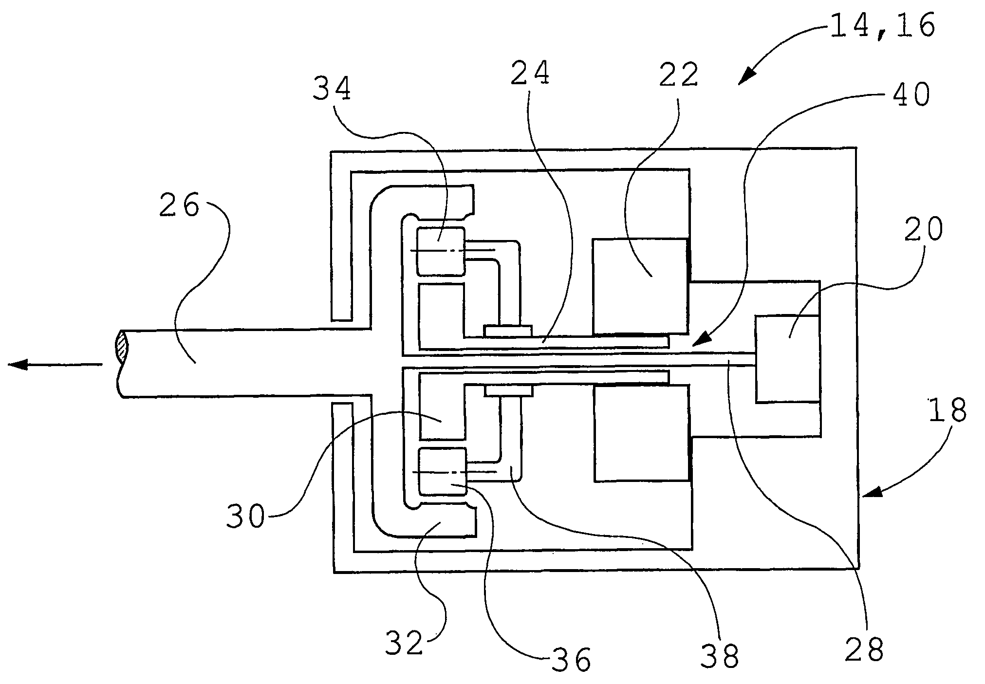
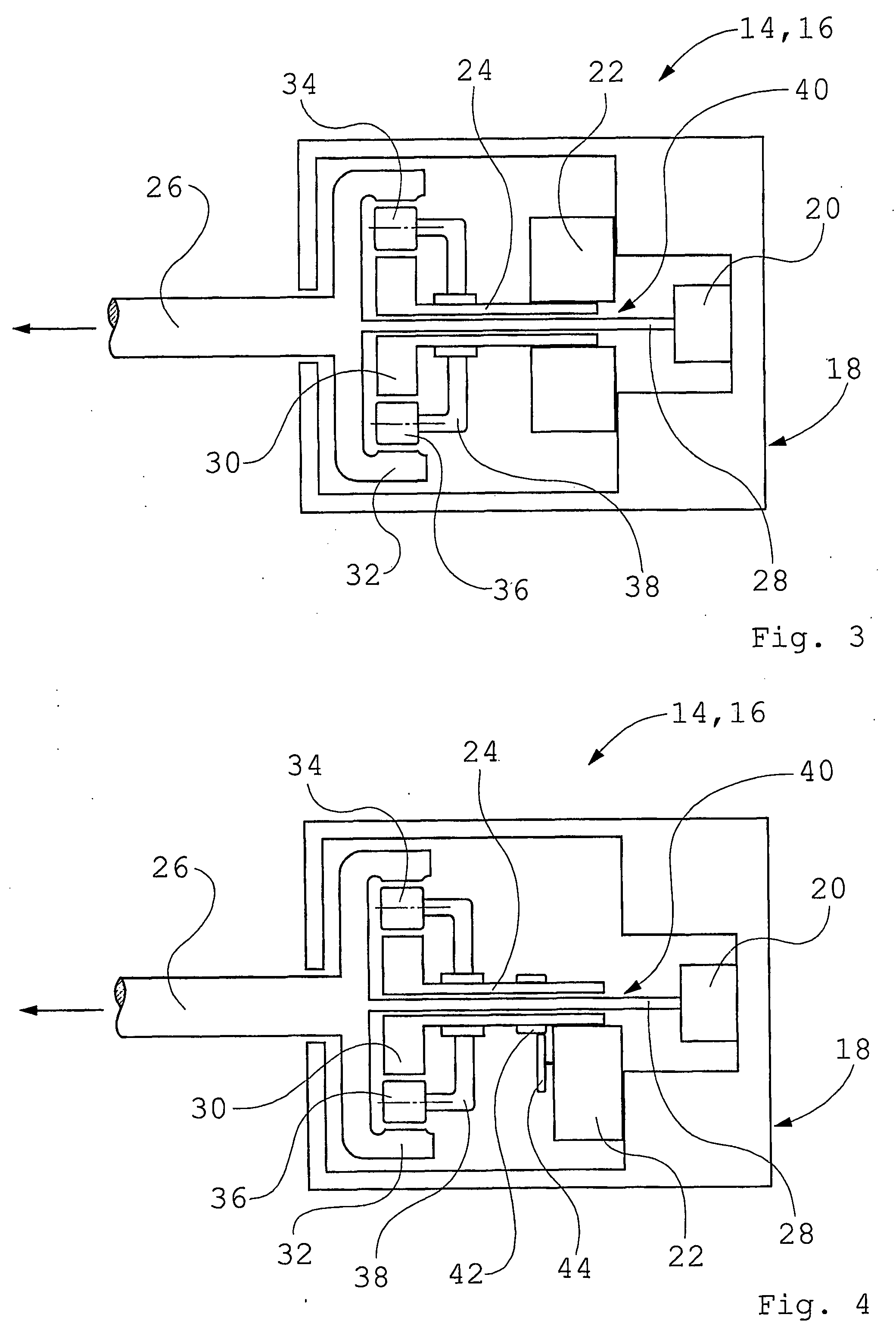
[0014]FIG. 3 shows schematically a sensor assembly according to the invention. The sensor assembly comprises a relative to a gearbox housing 18 fixed sensor 20, a propulsion motor 22, an input shaft 24 of the gearbox 14, 16, an output shaft 26 of the gearbox 14, 16, a to the output shaft 26 fixed shaft 28 which passes through the center of the gearbox 14, 16. In this embodiment the gearbox 14, 16 is a planetary gear whereby also inner sun wheel 30, outer sun wheel 32, planet pinions 34, 36 and planet pinion carrier 38 are shown in the figure. The shaft 28 which passes through the center of the gearbox 14, 16 can be fixed to the output shaft 26 by gluing, welding, or by mechanical fixing such as for example by use of splines, or in a similar way. Alternatively, the shaft 28 which passes through the center of the gearbox 14, 16 may be fixed to the output shaft 26 by that they are made in one piece. In this embodiment the propulsion motor 22 is a hollow piston engine with a central thr...

second embodiment

[0015]FIG. 4 shows schematically a sensor assembly according to the invention. This embodiment differs from that described in FIG. 3 only by that the propulsion motor 22 is arranged displaced from the center of the input shaft 24 of the gearbox 14, 16, whereby two toothed wheels 42, 44 are arranged to transfer the torque from the propulsion motor 22 to the input shaft 24 of the gearbox 14, 16.

[0016]The invention thus relates to a sensor assembly in a gearbox which is used for positioning, where the sensor assembly comprises a relative to the gearbox housing 18 fixed sensor 20, and where the angle between the gearbox housing 18 and the output shaft 26 of the gearbox 14, 16 is measured using a shaft 28 fixed to the output shaft 26 and connected to the sensor 20.

[0017]When positioning using a gearbox it is important to have end positions for the rotation so that one does not damage hoses etc. This can be done using mechanical stop devices but the disadvantage is that these must be stro...


PUM


Abstract

The invention relates to a sensor assembly in a gearbox which is used for positioning, where the sensor assembly comprises a relative to the gearbox housing (18) fixed sensor (20), and where the angle between the gearbox housing (18) and the output shaft (26) of a gearbox (14, 16) is measured using a to the output shaft (26) fixed and to the sensor (20) connected shaft (28), whereby a sensor assembly which measures the angle in the gearbox (14, 16) including the play in the gearbox (14, 16) is attained, which gives increased precision at the same time as gearboxes (14, 16) with play can be utilized for accurate angle positioning.

Description

TECHNICAL FIELD[0001]The present invention relates to a sensor assembly in a gearbox.BACKGROUND[0002]On modern rock drilling rigs, the positions of the drill booms are measured in order to be able to drill the holes in the correct place in the rock, possibly by using automatic controls. When measuring a position for a drill hole, the angles are measured at each joint of the drill booms and any telescopic movements of these. A boom has normally five to six joints, for which reason the measuring must be carried out with a high degree of precision in order to be able to calculate where the hole will be drilled.[0003]In those instances where gearboxes are used in order to achieve the rotations in the joints of the drill booms, normally the angle in the gearbox is measured by measuring on the input motor shaft, whereby one multiplies with the gear ratio of the gearbox.[0004]The problem with using a sensor assembly which measures the angle in the gearbox by measuring on the input motor sh...

Claims


Application Information

Patent Timeline
Patent Type & Authority Applications(United States)
IPC IPC(8): G05B19/404E21B15/00
CPCE21B7/022Y10T74/19219E21B7/025E21B15/00G05B19/404
Inventor SAF, FREDRIK
Owner EPIROC ROCK DRILLS AB
Why Eureka
Try Eureka