Method and apparatus for the production of hollow molded articles and a hollow molded article made by the method

a technology of hollow molded articles and methods, which is applied in the direction of rigid pipes, screw threaded joints, applications, etc., can solve the problems of insufficient physical insufficient strength of extruded pipes, and insufficient thickness of extruded pipes. achieve the effect of greater forces

Inactive Publication Date: 2008-06-12
SCOTT KENNETH LATIMER
View PDF6 Cites 8 Cited by
  • Summary
  • Abstract
  • Description
  • Claims
  • Application Information

AI Technical Summary

Benefits of technology

[0006]The present invention is based on the realisation that by utilising relatively short injection molded pipe sections which can be fitted together it is possible to apply greater forces to push the new pipe along the interior of the older one since each new pipe section can have force applied to its rearward end rather than its leading end at an intermediate point, which would be necessary to be able to apply the technique to a long length of extruded pipe. Further, the use of injection molded pipes makes it possible to adopt a new form of coupling which does not involve the use of external sleeves and which, therefore, leaves both the external surface and the internal surface of the pipeline substantially continuous and uninterrupted even at junctions between adjacent pipe sections.
[0007]The production of pipes by injection molding has a number of advantages, among which are the fact that the wall thickness can be made constant, and the material used need not be one suitable for the more conventional extrusion process by which very long lengths of pipe are currently made.
[0012]The pressurised fluid performs two functions, namely not only that of lubricant between the outer surface of the mandrel and the inner surface of the molded article, but also as a separating agent or release agent serving to space the material of the molded article from the mandrel, thereby compressing the molded article against the outer die parts to maintain the density of the injection molded article, provide it with a cooling effect, and promote release of the mandrel at the same time.
[0013]In a preferred arrangement the pressurised fluid is delivered through passages in the mandrel to openings in the surface thereof. Such openings are preferably of a shape and size such that at least one dimension is small enough to prevent the plastics material to be injection molded from entering the openings upon introduction into the mold cavity, for which purpose, of course, a preliminary pressure can be applied to the passages within the mandrel during introduction of the material which is to form the molded article. It is important in this respect that escape routes are provided for any fluid entering the mold cavity other than the plastics material to be molded so that no unwanted formations are caused as a result of the presence of the pressurizing fluid in the mold cavity during molding.
[0021]At least one dimension of each of the said openings in the said part of the surface of the mandrel is preferably such as to inhibit the entry of the plastics material upon injection thereof into the mold cavity. This can be achieved by a plurality of small circular openings, or by elongate slot-like openings which have the advantage of each providing a greater cross-sectioned area for the flow of fluid whilst nevertheless inhibiting ingress of plastics material during molding due, for example, to the surface tension of the injected plastics material.
[0033]A pipe section formed according to the invention may further be provided with surface formations, such as knurling, adjacent the screw-threaded portions on the external surface of the pipe, whereby to facilitate the screwing together of successive pipe sections by ensuring that handling apparatus is able to obtain the secure grip for rotating the pipe around its longitudinal axis.

Problems solved by technology

Extruded pipe has certain disadvantages, however, in particular the wall thickness is not absolutely constant because of the variation in process parameters during extrusion and the arrangements made for connection of adjacent pipe sections requires external sleeves which are necessarily larger in diameter than the diameter of the pipe.
However, when it comes to the reinstatement of degraded pipes resulting either from traffic overload or from the depredations of time, the physical strength of extruded pipe is insufficient to allow certain of the techniques which might be used for this purpose to be employed.
The expense and difficulty of excavating existing pipelines for the purpose of replacement make this course acceptable only if there are no alternatives.
However, the strength of the wall of the new pipe being introduced determines how much force can be applied to overcome the frictional resistance of its introduction, and if long lengths of pipe were to be used such force would be enormous and impractical.
In circumstances where the cohesion of the pipeline has been damaged and its integrity corrupted the necessity for a mole or ‘pig’ to be introduced first to ream out the bore complicates the issue and increases the cost.
However, the injection molding of elongate articles such as pipe sections has been fraught with difficulty because of the necessity to utilise an internal mandrel within the mold cavity to define the internal curved surface.
Collapsible mandrels which require to be assembled and dismantled prior to and after use have been tried, but this is expensive, makes the molding cycle longer and, furthermore, frequently results in the production of elongate flashing lines within the interior of the pipe.

Method used


Image

  • Method and apparatus for the production of hollow molded articles and a hollow molded article made by the method
  • Method and apparatus for the production of hollow molded articles and a hollow molded article made by the method
  • Method and apparatus for the production of hollow molded articles and a hollow molded article made by the method

Examples


Embodiment Construction

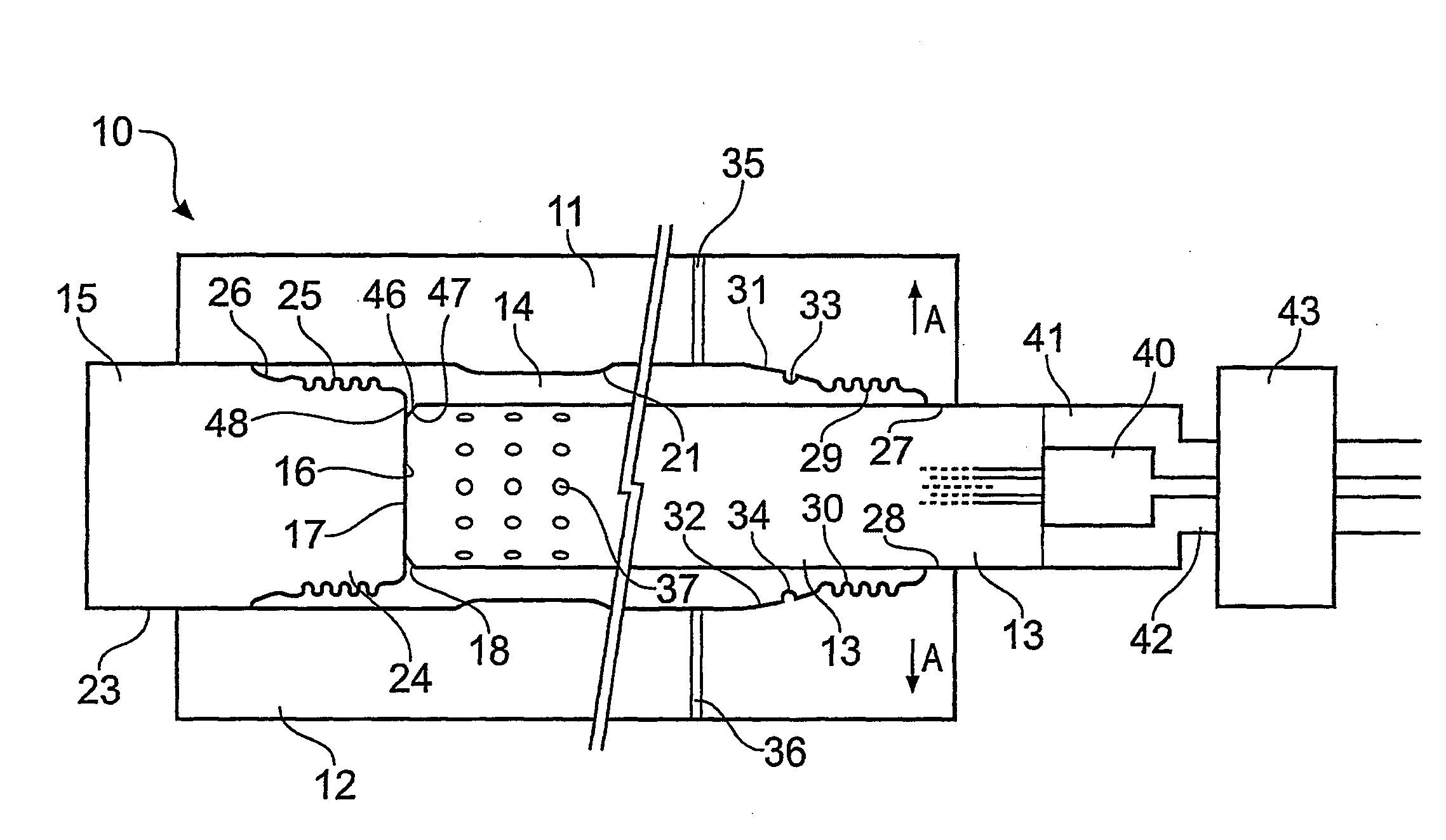
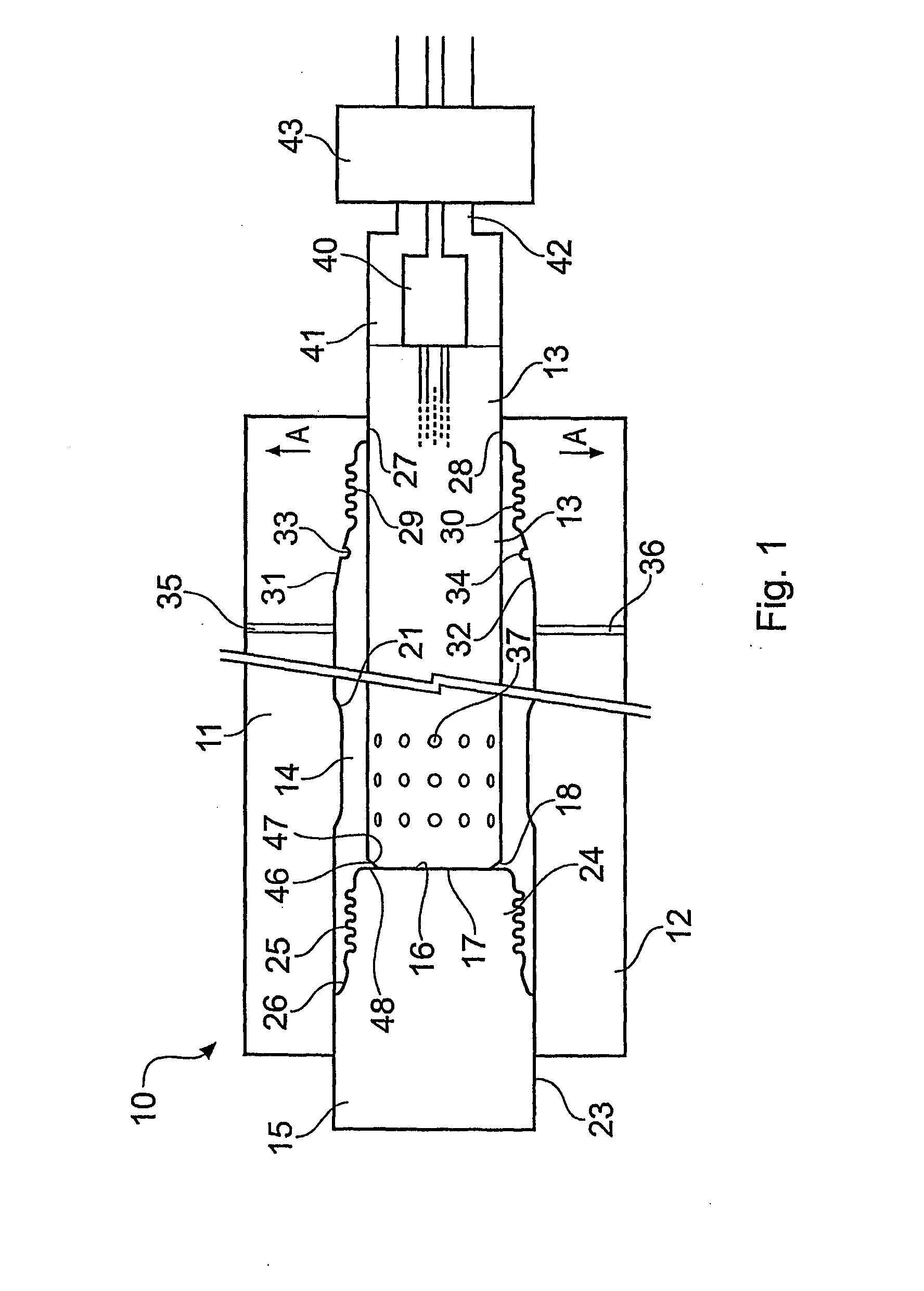
[0045]Referring first to FIG. 1, there is shown a multi-part mold structure 10 for forming a cylindrical article about a centre line CL. The mold structure 10 essentially comprises upper and lower main mold parts 11, 12 defining a mold cavity within which is located an elongate mandrel 13. The mold is significantly longer than it is wide, in order to make a molded article approximately one half of a metre in length and ten centimetres in diameter. For this reason the two ends of the mold have been shown in detail with a break line in the centre which represents the extended length of the mold.

[0046]The two mold parts 11, 12 and the mandrel 13 define an annular mold cavity generally indicated 14 having specific features which will be described in more detail below.

[0047]At the left hand end as viewed in FIG. 1 the mold cavity 14 is closed by a terminal mold part 15 which is shaped with a flat end face 16 which engages tightly with the corresponding flat end face 17 of the mandrel 13....


PUM

PropertyMeasurementUnit
lengthaaaaaaaaaa
areaaaaaaaaaaa
pressureaaaaaaaaaa

Abstract

A method of producing an injection-molded plastics article having a hollow interior, such as a pipe section comprising the steps of forming a mold cavity having outer dye parts and an inner mandrill to define an annular mold cavity. Then introducing plastics material into the mold cavity and delivering a pressurized fluid to the interface between the mandrill and the inner surface of the molded article through passages in the mandrill opening to the surface thereof, and withdrawing the mandrill while maintaining the outer dye parts in a closed condition. In addition, an apparatus for producing such hollow molded article, the hollow molded article itself, and a method of lining an aged, broken or damaged pre-existing pipeline are also described.

Description

1. PRIOR APPLICATION DATA[0001]This application claims priority to PCT Application No. PCT / GB2006 / 002230, entitled Method and Apparatus for the Production of Hollow Moulded Articles and a Hollow Moulded Article Made By the Method which was published as WO 2006 / 136796 and which is based on and claims priority to Great Britain patent application number 0512630.5 filed Jun. 21, 2005.2. FIELD OF THE INVENTION[0002]The present invention relates generally to the production of hollow molded articles, preferably by injection molding of plastics material, and particularly, but not exclusively, to the production of elongate pipes.3. RELATED ART[0003]Modern plastics pipe for drainage purposes is, in the main, produced by extrusion, which has a number of advantages including the ability to produce relatively long lengths of pipe, which are then coiled for transport and laid into trenches upon installation. Extruded pipe has certain disadvantages, however, in particular the wall thickness is not...

Claims


Application Information

Patent Timeline
Patent Type & Authority Applications(United States)
IPC IPC(8): B29C45/00B29C45/26B29C45/43F16L9/127F16L15/00F16L47/06F16L47/16
CPCB29C45/261B29C45/43B29L2023/22F16L47/16F16L15/008F16L47/065F16L9/127B29C33/42B29C33/424B29C33/46B29C45/40B29C45/435B29D1/00B29D23/00
Inventor SCOTT, KENNETH LATIMER
Owner SCOTT KENNETH LATIMER
Why Eureka
Try Eureka