Self-regulating permanent magnet device

a permanent magnet, self-regulating technology, applied in the direction of dynamo-electric converter control, magnetic circuit rotating parts, magnetic circuit shape/form/construction, etc., can solve the problems of limited maximum speed of permanent magnet motors, impracticality of pmgs in a number of applications,

Inactive Publication Date: 2008-06-12
HAMILTON SUNDSTRAND CORP
View PDF18 Cites 16 Cited by
  • Summary
  • Abstract
  • Description
  • Claims
  • Application Information

AI Technical Summary

Benefits of technology

[0007]A self-regulating permanent magnet device is comprised of a first rotor segment having a first compliment of permanent magnets and a second rotor segment having a second compliment of permanent magnets. The back electromotive force (bemf) generated in the stator windings of the self-regulating permanent magnet device is regulated by modifying the relative position of the second rotor segment relative to the first rotor segment. A first shaft is connected to the first rotor segment, and a second, coaxial shaft is connected to provide bearing and support to the second rotor segment as well as a cooling device. A torsion spring is connected between the first shaft and the seco

Problems solved by technology

This drawback makes PMGs impractical in a number of applications, or requires PMGs to include additional hardware such as shunt voltage regulators in order to reduce AC voltage generated at increased rotor speeds.
The interaction between the magnetic fields

Method used


Image

  • Self-regulating permanent magnet device
  • Self-regulating permanent magnet device
  • Self-regulating permanent magnet device

Examples


Embodiment Construction

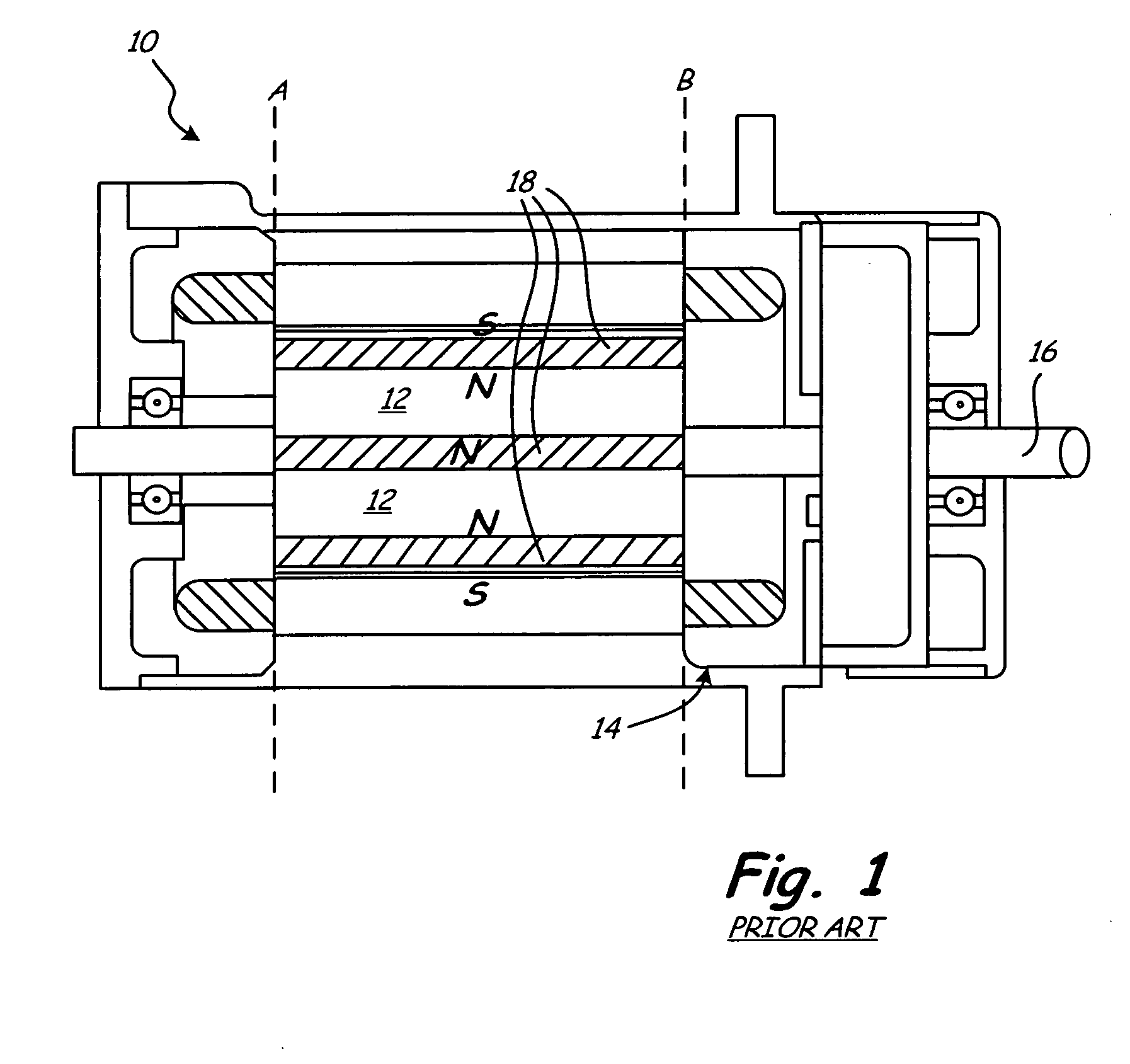
[0013]FIG. 1 is a broken cross-sectional view of a standard permanent magnet device (“PMD”) 10 as known in the prior art. PMD 10 includes rotor 12, stator 14, and shaft 16. Within the dashed line labeled A and B is a cross-sectional view that provides an unobstructed view of rotor 12 and the location of associated permanent magnet set 18. Outside of dashed lines 1A and 1B is a cross-sectional view of stator 14 and shaft 16, wherein shaft 16 is connected to provide / receive rotational energy to / from rotor 12, depending on whether PMD 10 is used in a generator or motor application.

[0014]Rotor 12 supports at least one permanent magnet set 18, wherein each permanent magnet included in the set has a magnetic north pole and a magnetic south pole. In a generator application, mechanical energy provided by shaft 16 causes rotor 12 and associated permanent magnet set 18 to rotate. The rotating permanent magnets generate a rotating magnetic field that interacts with the stator coils (not shown)...


PUM


Abstract

A self-regulating permanent magnet device has a first rotor segment and second rotor segment, each supporting a set of permanent magnets, wherein the position of the second rotor segment relative to the first rotor segment is modified based on the speed of the self-regulating permanent magnet device. By modifying the position of the second rotor segment relative to the first rotor segment, the alignment between their respective sets of permanent magnets, and therefore, the electromotive force (emf) generated in the stator coils is regulated. The position of the second rotor segment is defined by the connection of a torsion spring between the first rotor segment and second rotor segment and a reactionary torque device connected to the second rotor segment. The torsion spring creates a spring force that acts to maintain the alignment between the first rotor segment and the second rotor segment. The reactionary torque device provides reactionary torque that is proportional to the speed of the self-regulating permanent magnet device and opposes the spring force. As the speed of the self-regulating permanent magnet device increases, the reactionary torque causes the second rotor segment to rotate, thereby creating a misalignment between the first rotor segment and second rotor segment.

Description

BACKGROUND OF THE INVENTION[0001]The present invention relates to electromagnetic devices such as permanent magnet alternators and permanent magnet motors.[0002]Alternators are electromechanical devices that convert mechanical energy to alternating current (AC) electrical energy. Alternators employ a rotor to provide a rotating magnetic field that interacts with stator windings (i.e., conductors wound in coils around an iron core) to cause AC voltage to be generated. The magnitude of the AC voltage generated within the stator windings is directly related to the speed of the rotor and the strength of the magnetic field generated by the rotor.[0003]Generating the magnetic field in the rotor can be done in a number of ways. For example, in wound field synchronous alternators, the rotor may include coils (commonly referred to as field windings) that are energized by providing current to the field windings. The AC power generated by the wound field synchronous generator is controlled by ...

Claims


Application Information

Patent Timeline
IPC IPC(8): H02K16/02H02K9/04H02K21/00H02P9/00H02K1/27H02K7/14
CPCH02K21/029H02K16/02
Inventor POWERS, THEODORE CLIFTONHERNDEN, MICHAEL RAYMONDSHAH, MAHESH J.
Owner HAMILTON SUNDSTRAND CORP
Why Eureka
Try Eureka