Magnetic resonance imaging apparatus and magnetic resonance imaging method

a magnetic resonance imaging and apparatus technology, applied in the direction of nmr measurement, instruments, diagnostic recording/measuring, etc., can solve the problems of increasing imaging efficiency, unable to efficiently perform imaging, and difficulty in generating each image having desired image quality, etc., to achieve the effect of improving image quality and enhancing imaging efficiency

Inactive Publication Date: 2008-06-12
GE MEDICAL SYST GLOBAL TECH CO LLC
View PDF13 Cites 13 Cited by
  • Summary
  • Abstract
  • Description
  • Claims
  • Application Information

AI Technical Summary

Benefits of technology

[0034]According to the invention, there can be provided a magnetic resonance imaging apparatus and a magnetic resonance imaging method capable of easily improving image quality and enhancing imaging efficiency.

Problems solved by technology

Therefore, there may be cases where when the imaging area including the fluid is photographed at the subject, defective conditions such as the difficulty of generating each image having desired image quality, etc. are encountered.
Therefore, there may be cases in which imaging cannot be performed efficiently and a difficulty occurs in an increase in imaging efficiency.

Method used


Image

  • Magnetic resonance imaging apparatus and magnetic resonance imaging method
  • Magnetic resonance imaging apparatus and magnetic resonance imaging method
  • Magnetic resonance imaging apparatus and magnetic resonance imaging method

Examples


first embodiment

[0043]A first embodiment according to the invention will be explained.

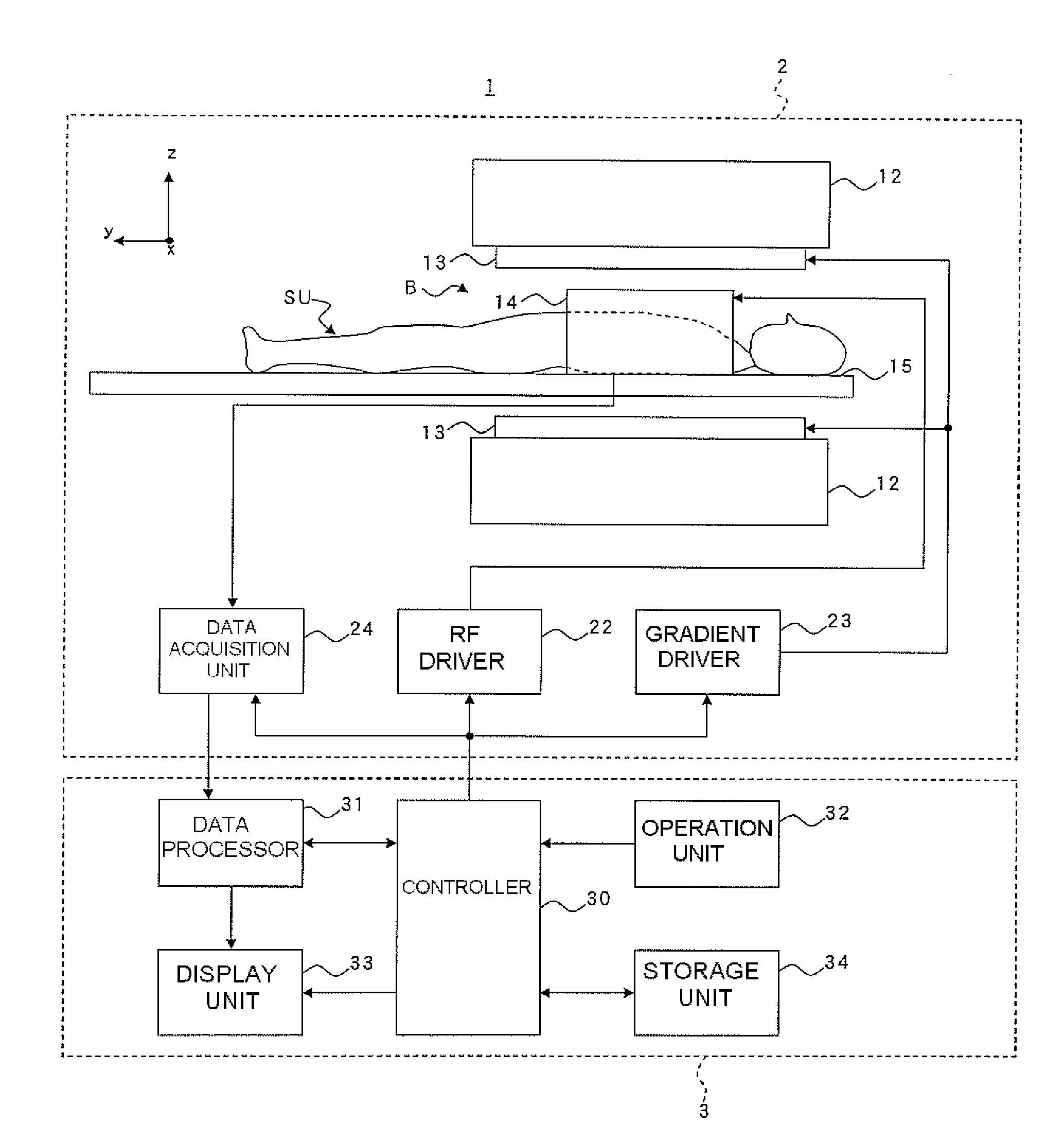
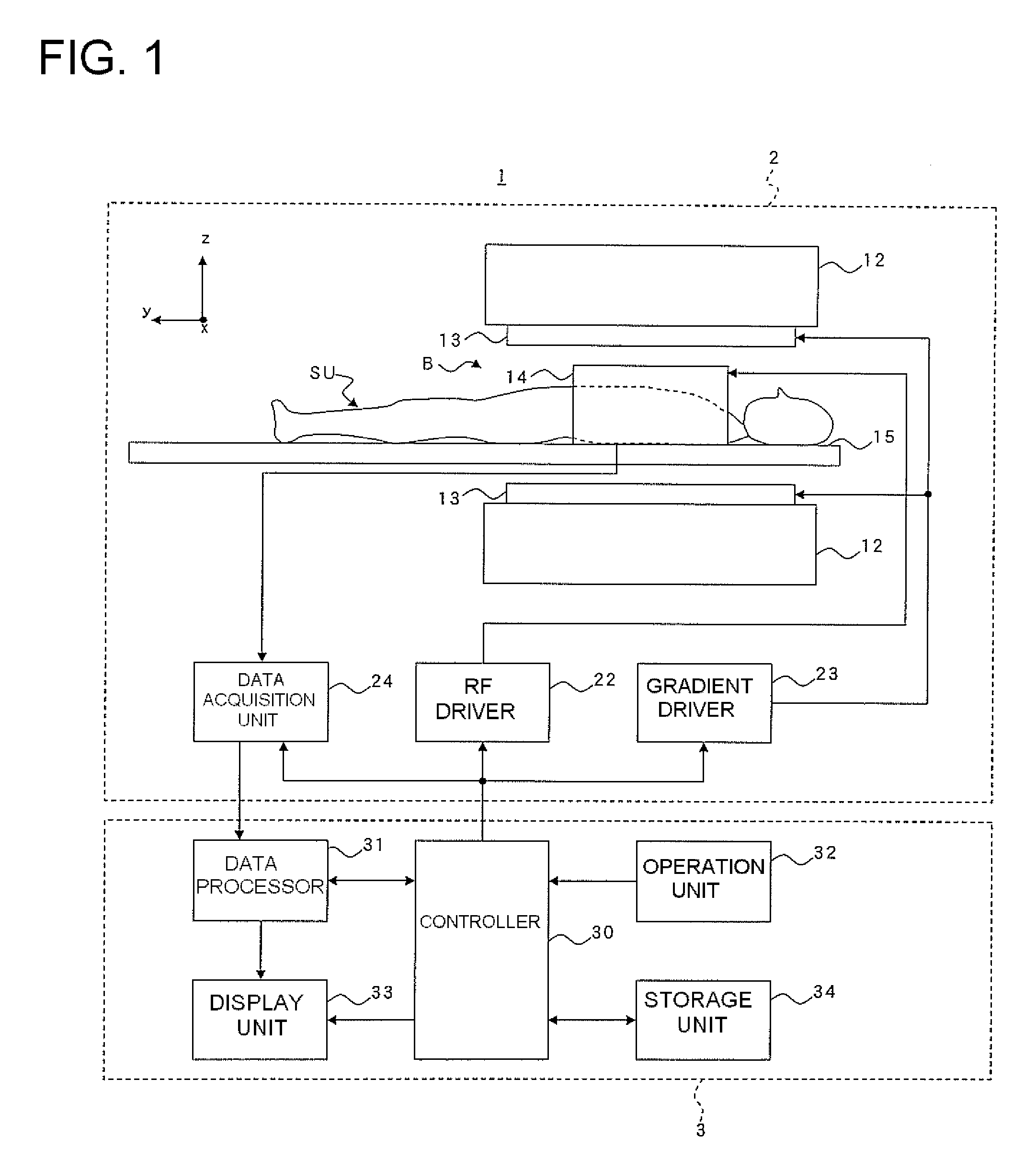
[0044](Apparatus construction) FIG. 1 is a block diagram showing a construction of a magnetic resonance imaging apparatus 1 illustrative of the first embodiment according to the invention.

[0045]As shown in FIG. 1, the magnetic resonance imaging apparatus 1 of the present embodiment has a scan section 2 and an operation console section 3.

[0046]The scan section 2 will be described.

[0047]As shown in FIG. 1, the scan section 2 has a static magnetic field magnet unit 12, a gradient coil unit 13, an RF coil unit or part 14, a cradle 15, an RF driver 22, a gradient driver 23 and a data acquisition unit 24. Here, the scan section 2 executes an imaging sequence IS for transmitting an RF pulse to a subject SU so as to excite spins in a subject SU within an imaging space B formed with a static magnetic field and transmitting a gradient pulse to the subject SU to which the RF pulse has been transmitted, thereby obtaining each...

second embodiment

[0121]A second embodiment according to the invention will be explained below.

[0122]The present embodiment is different from the first embodiment in terms of a scan effected on an imaging area of a subject SU. The present embodiment is similar to the first embodiment except for it. Explanations of dual spots or items will therefore be omitted.

[0123]FIG. 5 is a flowchart showing operation at the execution of the scan on the imaging area of the subject SU in the second embodiment according to the invention.

[0124]As shown in FIG. 5, a preparation sequence PS is first executed (S11).

[0125]Here, the scan section 2 performs the preparation sequence PS.

[0126]FIG. 6 is a pulse sequence diagram showing the preparation sequence PS employed in the second embodiment according to the invention.

[0127]In FIG. 6, RF indicates a time base on which RF pulses are transmitted, Gvenc indicates a time base on which velocity encode gradient pulses are transmitted, and Gkill indicates a time base on which k...


PUM


Abstract

With the objective of generating an imaging area including fluid with desired image quality at a subject and enhancing image quality, a first inversion recovery pulse is transmitted so as to invert spins in a second subject region which includes a first subject region used as the imaging area and is broader than the first subject region, before execution of a pulse sequence corresponding to an FSE method at every TR in an imaging sequence. After the execution of the pulse sequence corresponding to the FSE method, a second refocus pulse is transmitted so as to cause spins in a third subject region including the first subject region and wider than the first subject region to reconverge. A fast recovery pulse is transmitted to selectively recover spins in the first subject region. Thereafter, a second inversion recovery pulse is transmitted so as to invert the spins in the second subject region.

Description

BACKGROUND OF THE INVENTION[0001]The present invention relates to a magnetic resonance imaging (MRI) apparatus and a magnetic resonance imaging method. The present invention relates particularly to a magnetic resonance imaging apparatus and a magnetic resonance imaging method, which execute a scan for repeatedly executing, every time of repetition (TR: repetition time), an imaging sequence including a pulse sequence for sequentially transmitting an excitation pulse corresponding to an RF (Radio Frequency) pulse whose flip angle is 90°, and a plurality of refocus pulses each corresponding to an RF pulse whose flip angle is 180°, to a subject including fluid, so as to correspond to a fast spin echo (FSE) method in an imaging space formed with a static magnetic field, thereby obtaining magnetic resonance signals generated in an imaging area including the fluid at the subject, and generate images about the imaging area, based on the magnetic resonance signals obtained by executing the s...

Claims


Application Information

Patent Timeline
Patent Type & Authority Applications(United States)
IPC IPC(8): G01R33/483
CPCG01R33/5602G01R33/5635G01R33/5617G01R33/5607A61B5/055
Inventor MIYOSHI, MITSUHARU
Owner GE MEDICAL SYST GLOBAL TECH CO LLC
Why Eureka
Try Eureka