Pigment ink, ink set, ink jet recording method, ink cartridge, recording unit, ink jet recording apparatus, and image forming method

Active Publication Date: 2008-06-12
CANON KK
View PDF18 Cites 13 Cited by
  • Summary
  • Abstract
  • Description
  • Claims
  • Application Information

AI Technical Summary

Benefits of technology

[0031]According to the first invention aimed at the first object of the present invention, a pigment ink can be provided which is used in an ink jet recording apparatus in which ejection orifices for the pigment ink and ejection orifices for an ink that reacts with the pigment ink are capped with the identical cap, achieving compatibility between image quality and reliability.
[0032]According to the second invention aimed at the second object of the present invention,

Problems solved by technology

When plural inks having different hues are applied to a recording medium so as to be adjacent to each other in the ink jet recording method, there is a problem in that a phenomenon (bleeding) occurs in which the plural inks having different hues mix with each other at boundary portions between images formed from the inks.
In particular, the occurrence of bleeding at a boundary portion between images formed by a black ink and a color ink has a great influence on deterioration in image quality.
However, with ink jet recording apparatuses using ink, none of the above-mentioned techniques could sufficiently achieve a high level of reliability that has been requested in recent years.
However, in conventional techniques, emphasis has been placed on an efficient reaction between inks, that is, how to improve reactivity between inks for obtaining excellent bleeding resistance, hence sufficient reliability could not be obtained in some cases.
However, the use of such plural caps as described above results in an increase in size of an ink jet recording apparatus, the complication of the me

Method used


Image

  • Pigment ink, ink set, ink jet recording method, ink cartridge, recording unit, ink jet recording apparatus, and image forming method
  • Pigment ink, ink set, ink jet recording method, ink cartridge, recording unit, ink jet recording apparatus, and image forming method
  • Pigment ink, ink set, ink jet recording method, ink cartridge, recording unit, ink jet recording apparatus, and image forming method

Examples


examples

[0220]Hereinafter, the present invention will be described more specifically by way of examples and comparative examples. However, the present invention is by no means limited to these examples without departing from the gist of the present invention. The term “%” in the following description means “mass %” unless otherwise specified.

(Preparation of Pigment Ink)

(Preparation of Pigment Dispersion Liquid A)

[0221]1.5 g of 4-amino-1,2-benzenedicarboxylic acid in a state that it was cooled to 5° C. was added to a solution prepared by dissolving 5 g of concentrated hydrochloric acid in 5.5 g of water. Next, a container containing the solution was placed in an ice bath, and while the temperature of the solution was always kept at 10° C. or lower with stirring, a solution prepared by dissolving 1.8 g of sodium nitrite in 9 g of water at 5° C. was added to the solution. After the solution had been stirred for additional 15 minutes, 6 g of carbon black having a specific surface area of 220 m2...


PUM


Abstract

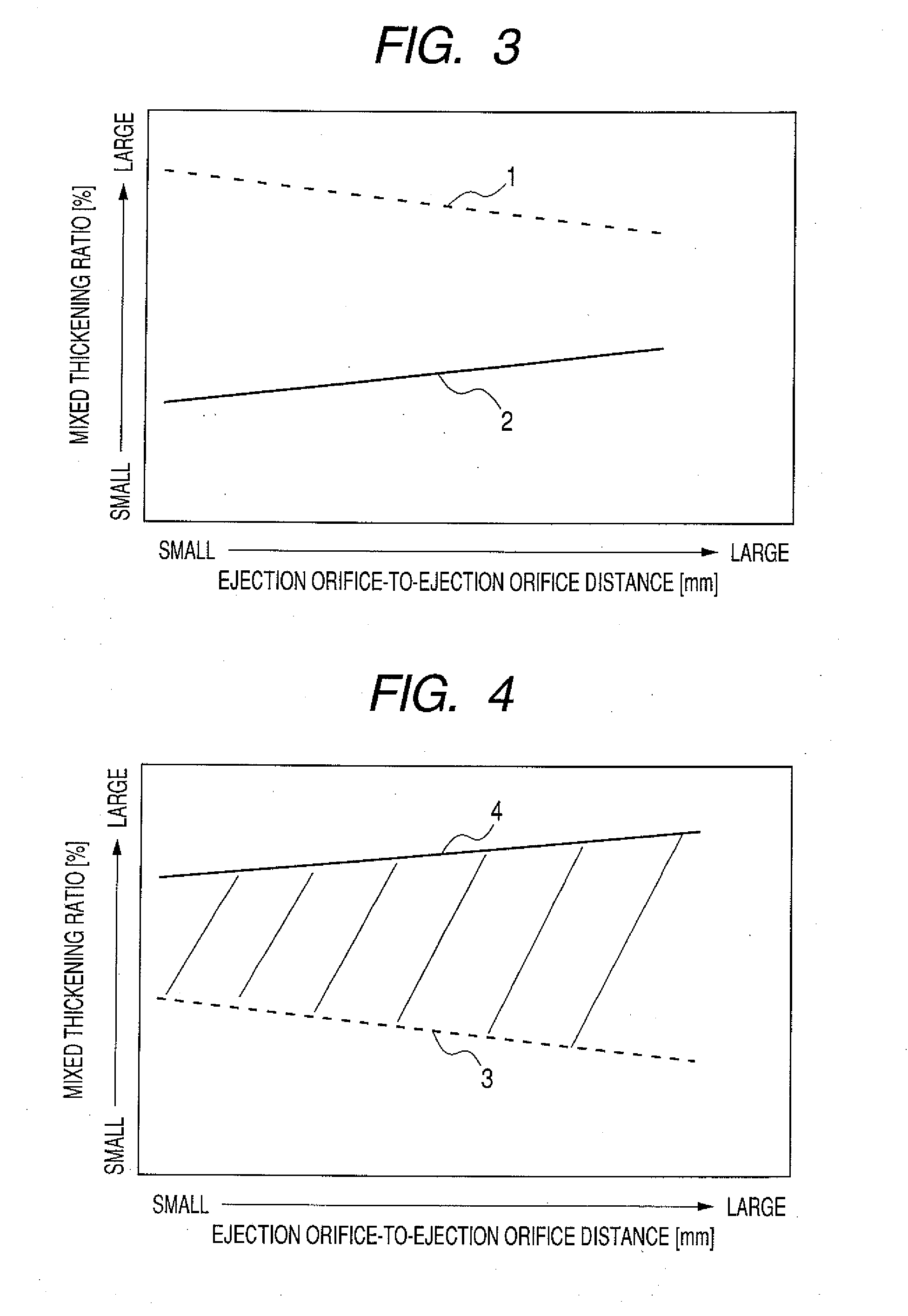
A pigment ink is provided which is used in an ink jet recording apparatus in which ejection orifices for a pigment ink and ejection orifices for at least one type of reactive ink that destabilizes a dispersed state of pigment in the pigment ink are capped with the identical cap provided with a unit for removing an ink in the cap, achieving compatibility between bleeding resistance and reliability. Where a mixed thickening ratio upon mixing the pigment ink and the reactive ink in equal volumes is represented by Y (%) and an ejection orifice-to-ejection orifice distance between the ejection orifice for the pigment ink and the ejection orifice for the reactive ink is represented by X (mm) (provided that X>0), Y and X satisfy a specific relationship.

Description

[0001]This application is a continuation of International Application No. PCT / JP2007 / 055159 filed on Mar. 8, 2007, which claims the benefit of Japanese Patent Application No. 2006-064315 filed on Mar. 9, 2006.BACKGROUND OF THE INVENTION[0002]1. Field of the Invention[0003]The present invention relates to a pigment ink, an ink set, an ink jet recording method, an ink cartridge, a recording unit, an ink jet recording apparatus, and an image forming method.[0004]2. Description of the Related Art[0005]An ink jet recording method is a method of recording an image involving ejecting ink onto a recording medium, and does not require a complicated apparatus, and hence a running cost can be suppressed to a low level, and, for example, a reduction in size of an ink jet recording apparatus and the colorization of images formed by the apparatus can be easily performed. Accordingly, various recording apparatuses employing the ink jet recording method, such as a printer, a copying machine, a facs...

Claims


Application Information

Patent Timeline
IPC IPC(8): B41J2/165G01D11/00
CPCC09D11/40C09D11/322B41J2/165B41J2/16508B41J2/16523B41J2/17513B41J2/1752B41J2/17553B41J2/2114
Inventor KAWABE, MINAKOTOMIOKA, HIROSHITAKUHARA, HIROYUKIYANAGIMACHI, SATOMINISHINO, YUUKI
Owner CANON KK
Why Eureka
Try Eureka