Discretely controlled micromirror array device with segmented electrodes

a micromirror array and segmented electrode technology, applied in the direction of mirrors, instruments, mountings, etc., can solve the problems of incompatibility with known semiconductor electronics technologies, micromirror arrays have difficulties in making micromirror arrays have desired surfaces, and analog control is more complex than digital or discrete control, etc., to achieve increased flexibility, strong electrostatic force, and increased flexibility

Active Publication Date: 2008-06-12
STEREO DISPLAY
View PDF5 Cites 17 Cited by
  • Summary
  • Abstract
  • Description
  • Claims
  • Application Information

AI Technical Summary

Benefits of technology

[0013]Still another objective of the invention is to provide a discretely controlled micromirror array device with structural stability and efficiency in motion.
[0040]The micromirrors in the micromirror array have independently controlled motions to make a spatial light modulator. The micromirrors in the spatial light modulator are controlled to retract or elevate to remove the phase aberration of an optical system. The one or two degrees of freedom rotation of the micromirrors is controlled to control light intensity. Also, the one or two degrees of freedom rotation of the micromirrors is controlled to scan a field of regard. Along with the rotational degrees of freedom, translational degree of freedom motion can be achieved to make a fine spatial light modulator.

Problems solved by technology

The analog control is more complex than the digital or discrete control, and is not compatible with known semiconductor electronics technologies such as MOS, CMOS, etc.
However, this micromirror array has difficulties to make a micromirror array have a desired surface profile simulating such as aspherical (e.g. parabolic, hyperbolic, elliptical, etc), or non-axis-symmetric lenses.
In this system, the attractive forces are applied to micromirror itself, which may cause a structural deformation due to residual stress leading to the degradation of the image quality.
Further, this system does not provide a micromirror array system capable of providing multiple surface profiles.
This system, however, is operated in the analog mode, which requires complex and fine control of voltage and can cause a snap down problem.
Further, the attractive forces are applied to micromirror itself, which may cause a structural deformation due to residual stress leading to the degradation of the image quality.

Method used


Image

  • Discretely controlled micromirror array device with segmented electrodes
  • Discretely controlled micromirror array device with segmented electrodes
  • Discretely controlled micromirror array device with segmented electrodes

Examples


Embodiment Construction

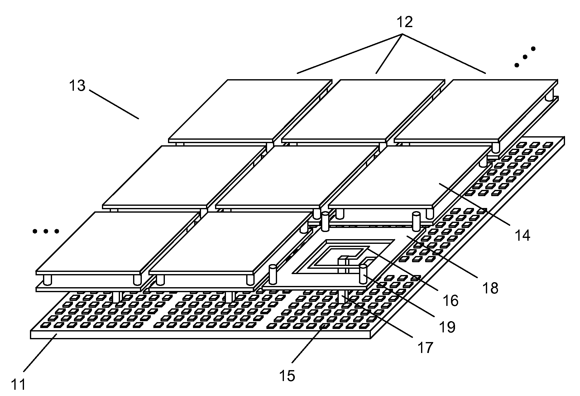
[0053]FIG. 1 shows a schematic illustration of a discretely controlled micromirror array device and the structures underneath a micromirror structure. A discretely controlled micromirror array device comprises a substrate 11 with a control circuitry (not shown) and a plurality of micromirrors 12 forming a micromirror array 13. Each micromirror 12 in the micromirror array 13 comprises a micromirror structure 14 having a reflective surface on one side, a plurality of segmented electrodes 15 disposed on the substrate surface and electronically coupled to the control circuitry for activating segmented electrodes 15 selectively, at least one flexible structure 16 for connecting the micromirror structure 14 and the substrate 11 and providing restoring force to the micromirror 12, and at least one pillar structure 17 for supporting the flexible structure 16 and providing connection between the substrate 11 and the flexible structure 16. The micromirror 12 further comprises at least one top...


PUM


Abstract

This invention provides a discretely controlled micromirror array device comprising a plurality of micromirrors. The discretely controlled micromirror array device forms multiple surface profiles, wherein the rotational and translational motion of each micromirror is discretely controlled by selectively activating different groups of segmented electrodes using a control circuitry. The discretely controlled micromirror array device is compatible with known semiconductor electronics technologies and provides structural stability and efficiency in motion.

Description

FIELD OF INVENTION[0001]The present invention relates to a micromirror array device. Particularly, the invention relates to discretely controlled micromirror array device providing multiple surface profiles, wherein each micromirror has independent motion of rotation and translation using segmented electrodes.BACKGROUND OF THE INVENTION[0002]Micromirror array devices have been developed because it can substitute for conventional optoelectronic devices. Phase-only piston-style micromirrors were used for phase adaptive optics applications, and rotational micromirrors were used to deflect light. These micromirrors have been controlled by analog control to have continuous displacement, which is determined at the equilibrium between electrostatic force and elastic force. The analog control is more complex than the digital or discrete control, and is not compatible with known semiconductor electronics technologies such as MOS, CMOS, etc.[0003]In the prior art of a micromirror array such a...

Claims


Application Information

Patent Timeline
Patent Type & Authority Applications(United States)
IPC IPC(8): G02B26/00
CPCG02B26/0841G09G2310/0221G09G3/346
Inventor KIM, HYE YOUNGGIM, DONG WOOSOHN, JIN YOUNGCHO, GYOUNG ILSEO, CHEONG SOO
Owner STEREO DISPLAY
Why Eureka
Try Eureka