
Apparatus and method for detecting horizon in sea image

Inactive Publication Date: 2008-06-12
ELECTRONICS & TELECOMM RES INST
View PDF34 Cites 16 Cited by
  • Summary
  • Abstract
  • Description
  • Claims
  • Application Information

AI Technical Summary

Benefits of technology

[0008]Accordingly, the present invention is directed to an apparatus and method for detecting a horizon in a sea

Problems solved by technology

It requires great effort and takes a lot of time to perform the composition in each frame by manual manipulation.
In addition, unlike a long-range shot is taken from a helicopter, when a close-range shot is taken from a neighboring ship, it is a problem the marker buoys are heavily moved by waves.
Accordingly, the image composition is very difficult in most cases.
However, the horizon cannot be detected using the line detection process because the horizon is blurred due to wet fog when weather condition is bad.

Method used


Image

  • Apparatus and method for detecting horizon in sea image
  • Apparatus and method for detecting horizon in sea image
  • Apparatus and method for detecting horizon in sea image

Examples


Embodiment Construction

[0031]Reference will now be made in detail to the preferred embodiments of the present invention, examples of which are illustrated in the accompanying drawings.

[0032]For convenience of description, the same names and symbols are used to refer to the same elements as the related art and their detailed description will be omitted.

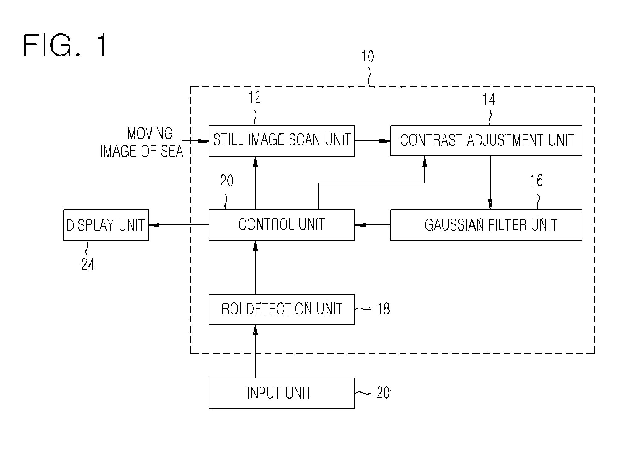
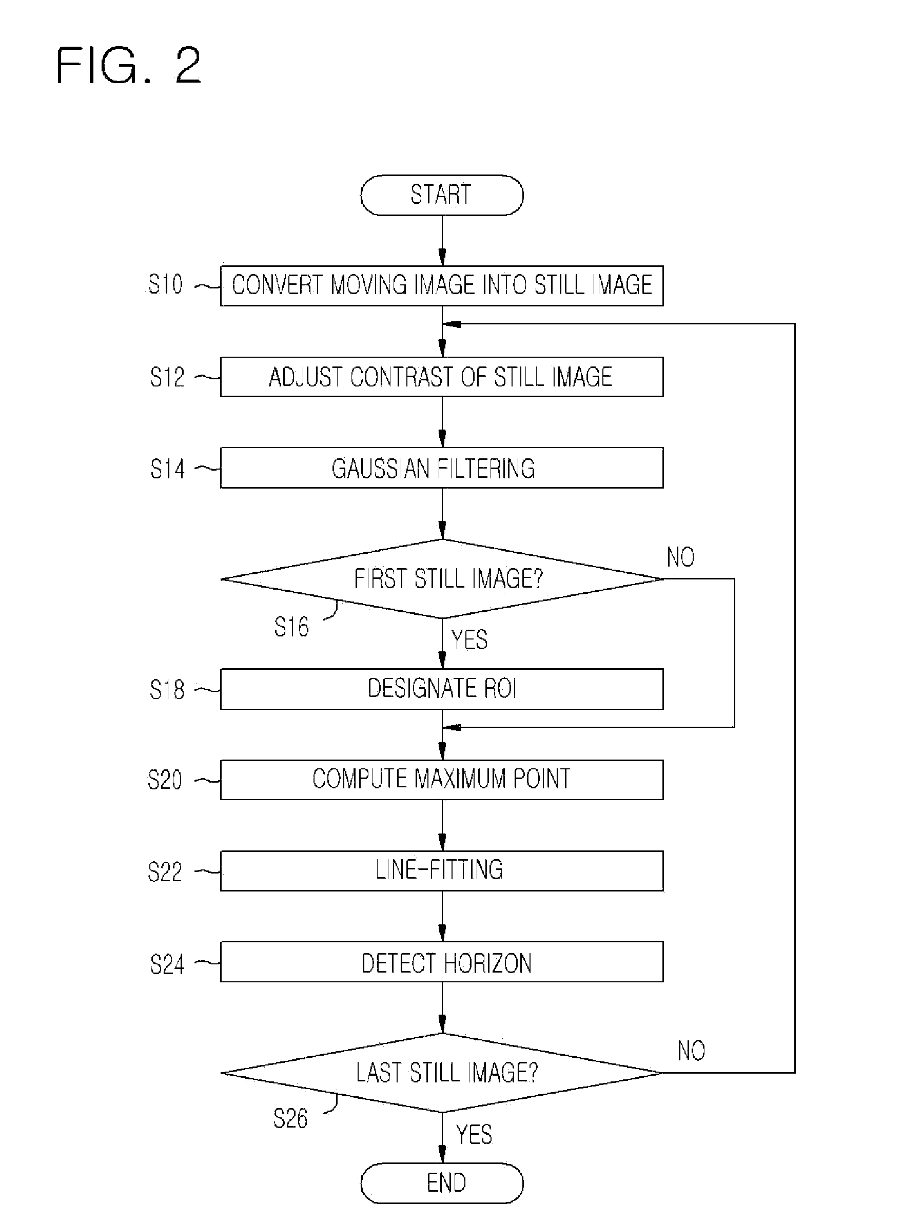
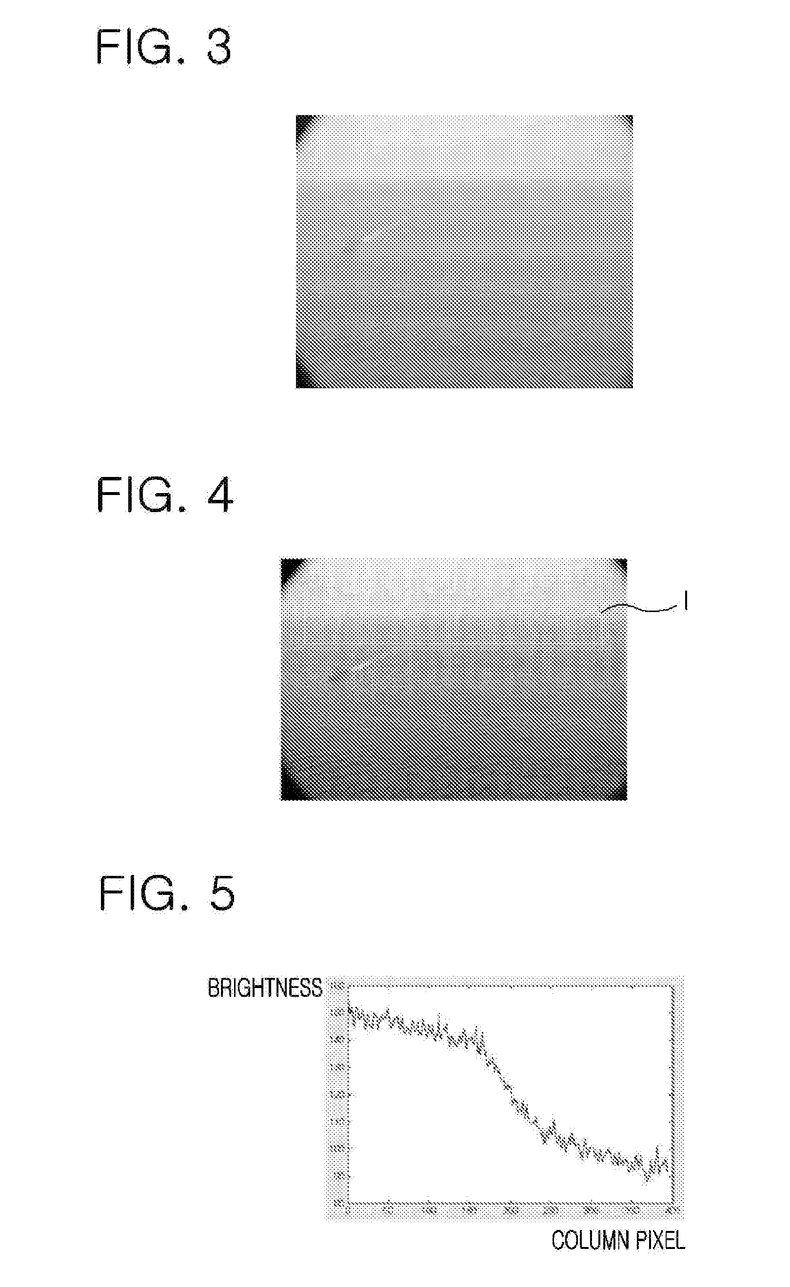
[0033]FIG. 1 is a block diagram of a horizon detecting apparatus according to an embodiment of the present invention, FIG. 2 is a flowchart of a horizon detecting method according to an embodiment of the present invention, FIG. 3 illustrates an original sea image having a blurred horizon, and FIG. 4 illustrates a designated ROI in a first still image in the moving image of the sea.

[0034]Referring to FIGS. 1 to 4, the horizon detecting apparatus 10 of FIG. 1 includes a still image scan unit 12, a contrast adjustment unit 14, a Gaussian filter unit 16, a region-of-interest (ROI) detection unit 18, and a control unit 20. The horizon detecting apparatus 10 is co...


PUM


Abstract

Provided is an apparatus and method for detecting a horizon which is necessary to detect a camera movement when compositing sea images in a marker-free sea-image camera tracking system. In the method, an ROI is selected near a horizon in a still image of the moving image of the sea, and each maximum point corresponding to the maximum brightness difference is detected from brightness differences between two pixels of each pair having two symmetrical pixels in each column of the ROI. The horizon is detected through a line-fitting using the maximum points. Therefore, the result of horizon detection can be very stable and a horizon can be easily detected in a sea scene having hundreds of frames.

Description

BACKGROUND OF THE INVENTION[0001]1. Field of the Invention[0002]The present invention relates to an apparatus and method for detecting a horizon in a sea image, and more particularly, to an apparatus and method for detecting a horizon which is necessary to detect a camera movement when compositing sea images in a marker-free sea-image camera tracking system.[0003]The present invention is drawn from a study conducted as a IT new driving force key technology development project of Ministry of Information and Communication (MIC), and Institute for Information Technology Advancement (IITA) [task reference number: 2005-S-003-02, task name: Photo-Realistic Digital Image Content Production Software].[0004]2. Description of the Related Art[0005]A compositing technique of computer graphics (CG) and real image is considerably developed in the movie industry and augmented reality. A camera movement at the moment of shooting should be detected for natural composition. It requires great effort a...

Claims


Application Information

Patent Timeline
IPC IPC(8): G06K9/46G06V10/25
CPCG06T2207/30184G06K9/3233G06V10/25
Inventor LEE, JAE KWANGPARK, CHANG JOONLEE, IN HO
Owner ELECTRONICS & TELECOMM RES INST
Learn More