Capacity Control Valve

a technology of capacity control and valve body, which is applied in the direction of valve operating means/release devices, machines/engines, positive displacement liquid engines, etc., can solve the problem that the desired discharge amount cannot be guaranteed by compressing the refrigerant gas, and achieve the effect of stable capacity control, reduced size and cos

Active Publication Date: 2008-06-12
EAGLE INDS +1
View PDF12 Cites 44 Cited by
  • Summary
  • Abstract
  • Description
  • Claims
  • Application Information

AI Technical Summary

Benefits of technology

[0026]According to the capacity control valve configured as above, since the liquid refrigerant accumulating in the control chamber can be rapidly discharged particularly immediately after start of the variable capacity compressor, the desired capacity control can be carried out rapidly and securely, and also, a capacity control valve which can achieve stable capacity control and reduction in entire size and costs can be obtained.

Problems solved by technology

When the swash plate type variable capacity compressor is stopped, left for a long time and to be started again, a liquid refrigerant (a refrigerant gas cooled during it is left and liquefied) accumulates in the control chamber (crank chamber), and a desired discharge amount can not be ensured by compressing the refrigerant gas unless this liquid refrigerant is discharged.

Method used


Image

  • Capacity Control Valve
  • Capacity Control Valve
  • Capacity Control Valve

Examples


Embodiment Construction

[0096]A preferred embodiment of the present invention will be described below referring to the attached drawings.

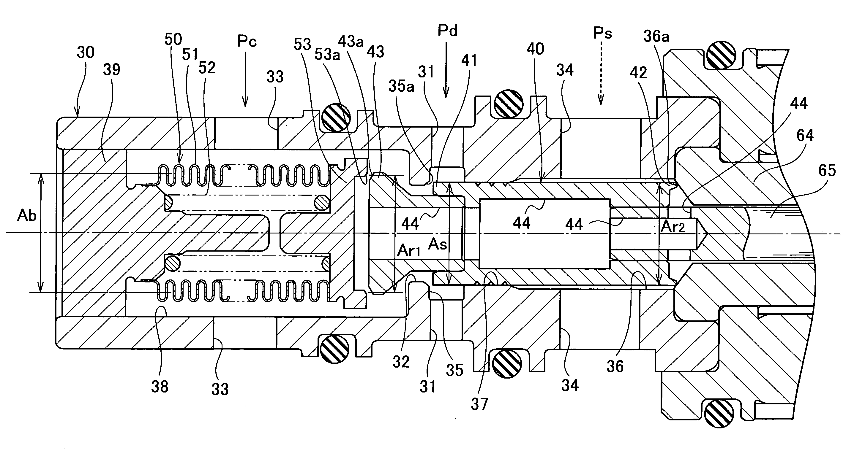
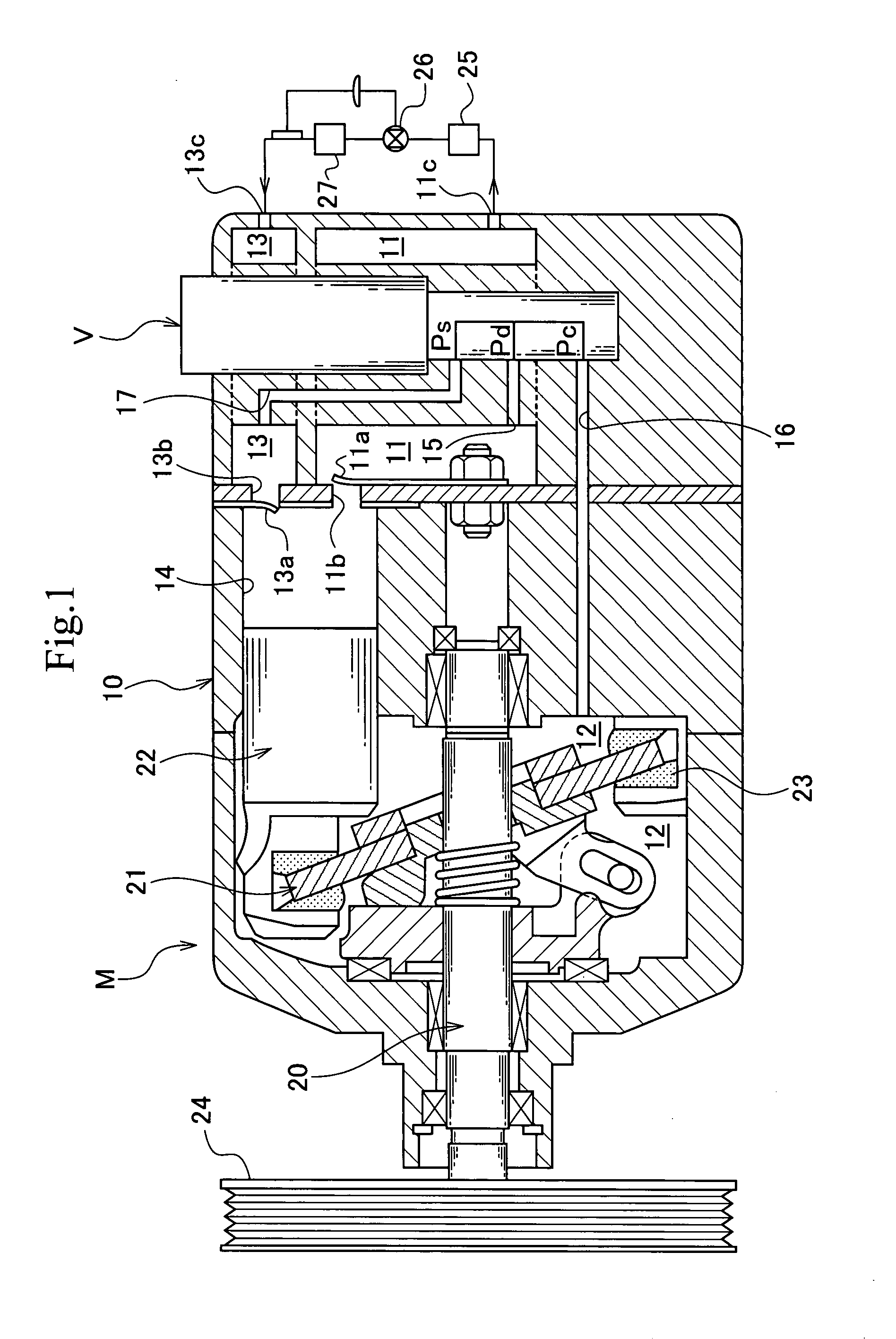
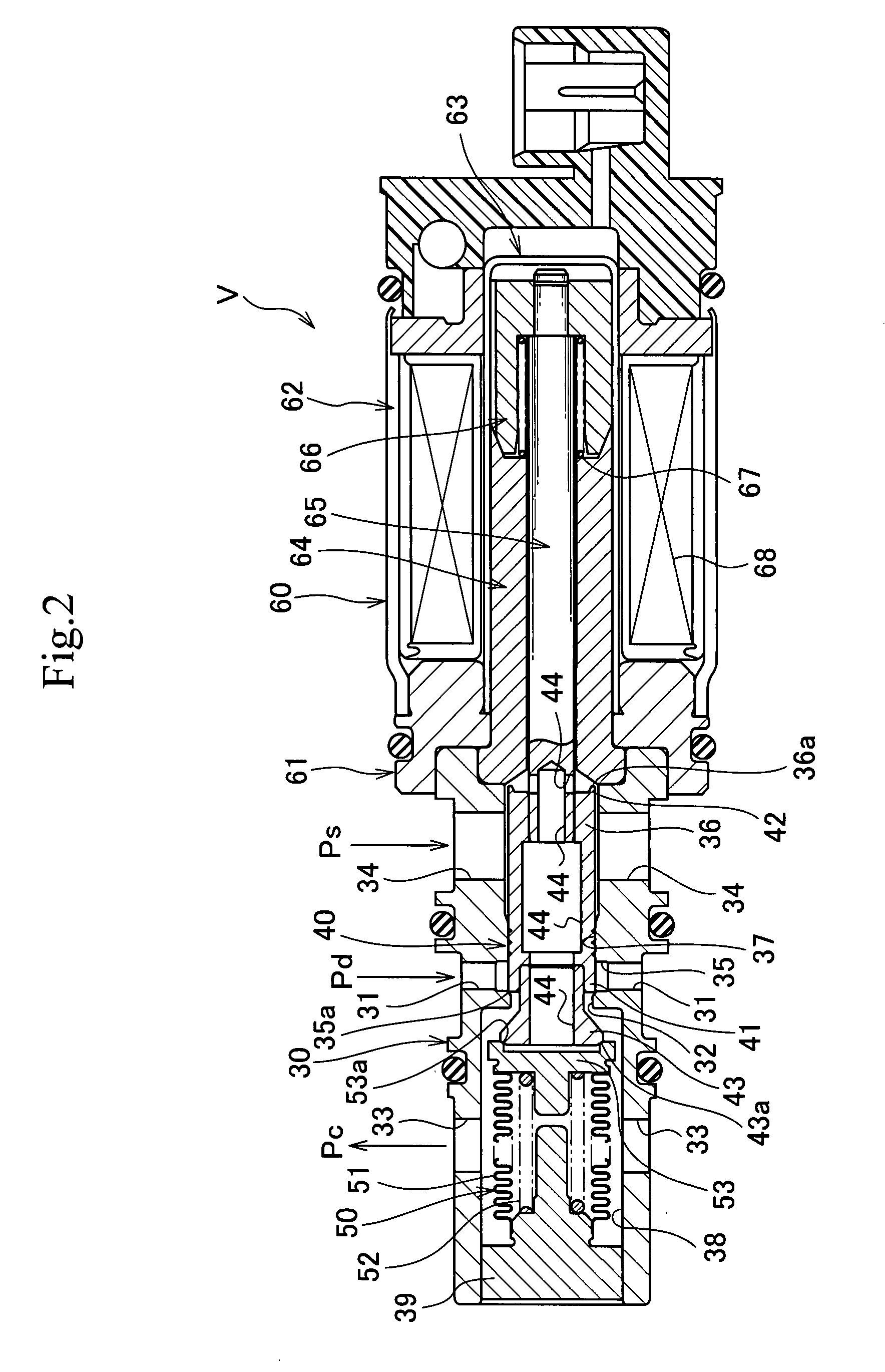
[0097]A swash plate type variable capacity compressor M includes, as shown in FIG. 1, a discharge chamber 11, a control chamber (also referred to as a crank chamber) 12, a suction chamber 13, a plurality of cylinders 14, a port 11b having the cylinders 14 communicate with the discharge chamber 11 and opened / closed by a discharge valve 11a, a port 13b having the cylinders 14 communicate with the suction chamber 13 and opened / closed by a suction valve 13a, a discharge port 11c and a suction port 13c connected to an external cooling circuit, a communication path 15 as a discharge-side path for having the discharge chamber 11 communicate with the control chamber 12, a communication path 16 serving as the above discharge-side path and serving as a suction-side path for having the control chamber 12 communicate with the suction chamber 13, a casing 10 defining a communication p...


PUM


Abstract

A capacity control valve of the present invention includes a valve body (40) integrally having a first valve portion (41) for opening / closing a discharge-side path for having a discharge chamber (11) communicate with a control chamber (12) and a second valve portion (42) for opening / closing a suction-side path for having a suction chamber (13) communicate with the control chamber (12), a pressure sensitive body (50) arranged in a third valve chamber (38) in the middle of the suction-side path, a valve seat body (53) provided at the pressure sensitive body (50), a third valve portion (43) connected to the valve body (40) for opening / closing the suction-side path by engagement and disengagement with the valve seat body (53) and the like. One of an engagement face 43a of the third valve portion and a seat face 53a of the valve seat body is formed into a spherical shape with a radius of curvature R satisfying 9 mm<R<11 mm and the other of the engagement face 43a of the third valve portion and the seat face 53a of the valve seat body is formed into a tapered surface shape having a center angle α satisfying 120°<α<160°. By this, a liquid refrigerant or the like accumulating in the control chamber can be discharged efficiently, and predetermined capacity control can be carried out rapidly.

Description

TECHNICAL FIELD[0001]The present invention relates to a capacity control valve for variable control of a capacity or pressure of a working fluid and particularly to a capacity control valve for controlling a discharge amount of a variable capacity compressor or the like used in an air-conditioning system of an automobile or the like according to a pressure load.BACKGROUND ART[0002]A swash-plate type variable capacity compressor used in an air-conditioning system of an automobile or the like is provided with a rotating shaft rotated and driven by a rotation force of an engine, a swash plate connected to the rotating shaft with a variable inclination angle, a piston for compression connected to the swash plate and the like, and by varying the inclination angle of the swash plate, a stroke of the piston is changed so as to control the discharge amount of a refrigerant gas.[0003]The inclination angle of the swash plate can be continuously changed by adjusting a pressure balance acting o...

Claims


Application Information

Patent Timeline
Patent Type & Authority Applications(United States)
IPC IPC(8): F04B27/18
CPCF04B27/1804F04B2027/1827F04B2027/1854F04B2027/1845F04B2027/1831Y10T137/86622F04B27/1018F04B49/22F04B27/0878F05B2210/12Y10S417/00
Inventor UMEMURA, SATOSHIOTA, MASAKIKAWAGUCHI, MASAHIROCHO, RYOSUKISHIRAFUJI, KEIGOIWA, TOSHIAKI
Owner EAGLE INDS
Why Eureka
Try Eureka