Etching Method and Etching Apparatus

Inactive Publication Date: 2008-06-12
TOKYO ELECTRON LTD
View PDF4 Cites 62 Cited by
  • Summary
  • Abstract
  • Description
  • Claims
  • Application Information

AI Technical Summary

Benefits of technology

[0012]In view of the above disadvantages, the present invention has been made to efficiently solve the same. The object of the present invention is to provid

Problems solved by technology

However, a reaction product such as WO3 and WClxOy (x and y respectively represent positive numbers), which is produced when a Cl-group gas is used as the etching gas, is disadvantageous in that such reduction product is prone to be deposited because of a relatively low volatility thereof.
On the other hand, when an F-group gas, which is

Method used


Image

  • Etching Method and Etching Apparatus
  • Etching Method and Etching Apparatus
  • Etching Method and Etching Apparatus

Examples


Embodiment Construction

[0037]An Embodiment of the etching apparatus and etching method of the present invention will be described in detail below with reference to the attached drawings.

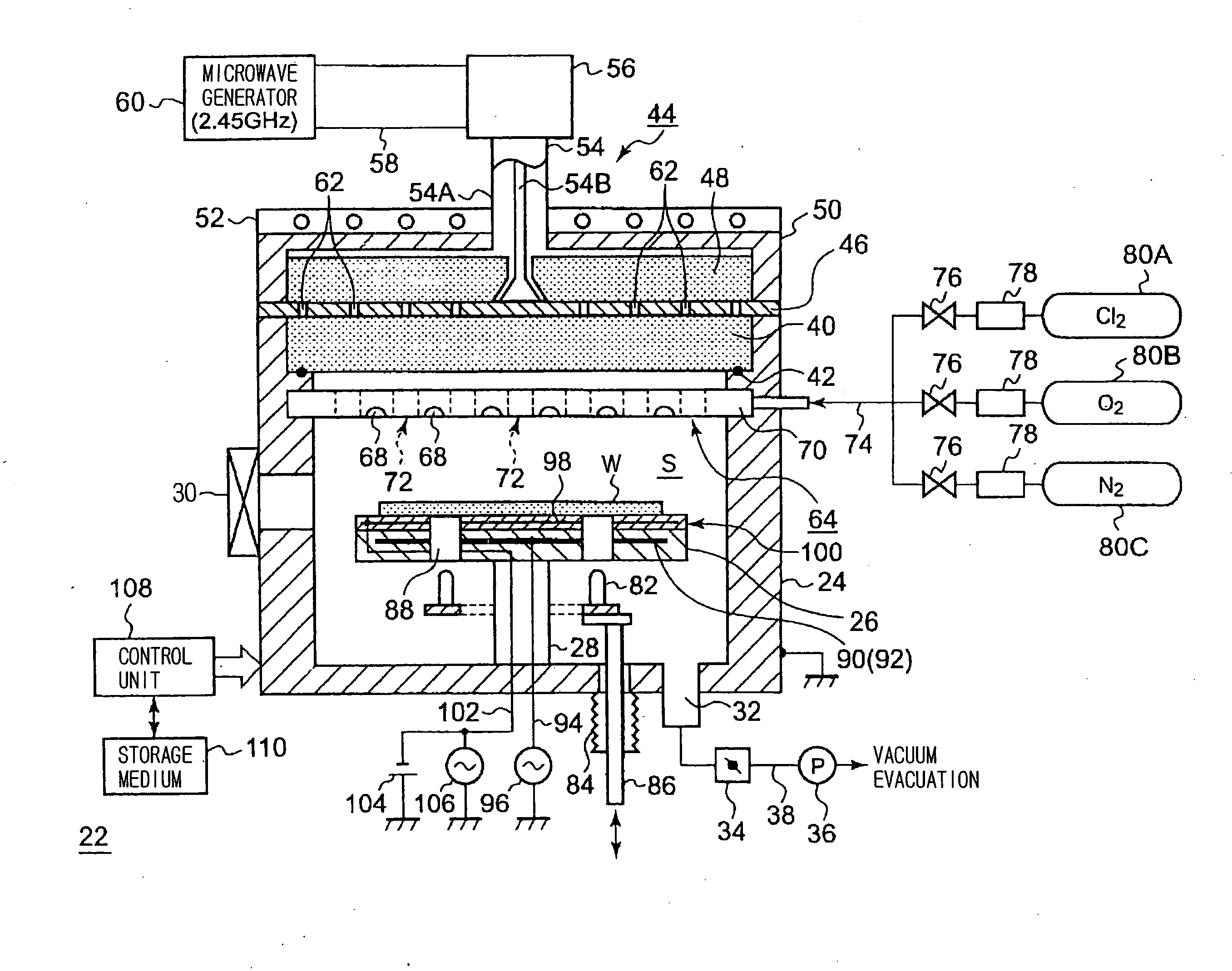
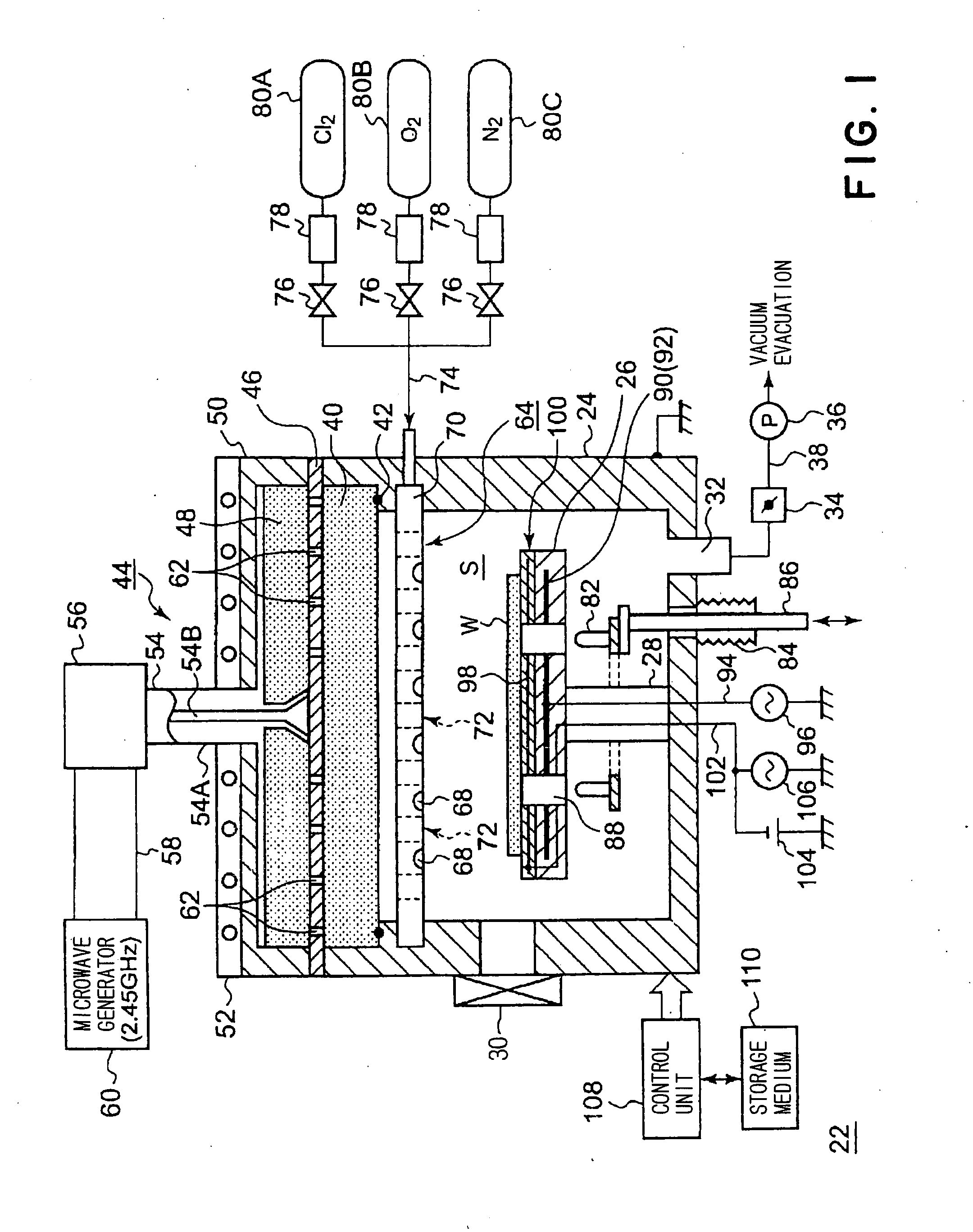
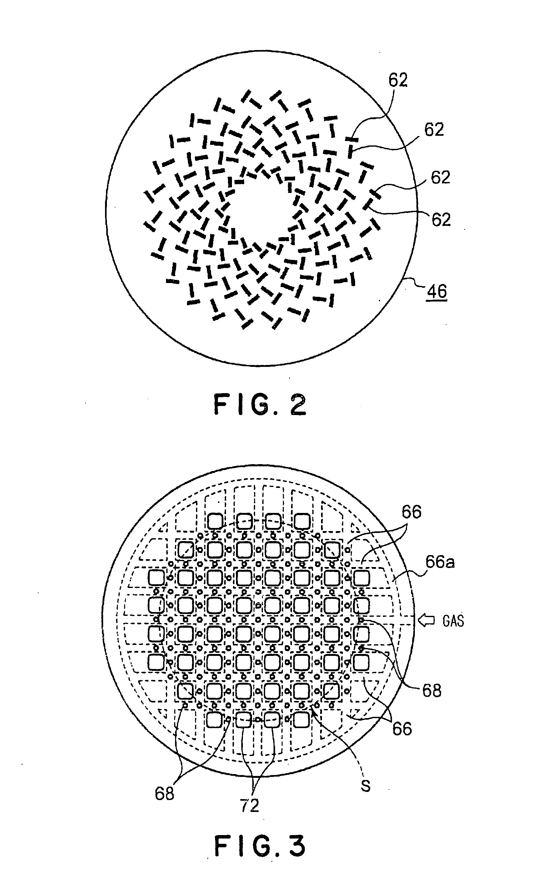
[0038]FIG. 1 is a schematic view of the etching apparatus in one embodiment of the present invention. FIG. 2 is a plan view of a planar antenna member of a plasma generating unit. FIG. 3 is a bottom view of a showerhead part of a gas supplying unit.

[0039]Herein, an etching apparatus using a planar antenna member of an RLSA type (Radial Line Slot Antenna) is described by way of an example.

[0040]As shown in FIG. 1, the etching apparatus 22 in this embodiment includes a process vessel 24 of generally a cylindrical shape. The process vessel 24 has a sidewall and a bottom part, which are formed of a conductive material such as aluminum and are grounded. An inside of the process vessel 24 provides a hermetically sealed process space S in which a plasma is generated.

[0041]The process vessel 24 accommodates a stage 26 on which an ...


PUM

PropertyMeasurementUnit
Fractionaaaaaaaaaa
Fractionaaaaaaaaaa
Fractionaaaaaaaaaa

Abstract

The present invention is an etching method for performing an etching process in the presence of a plasma on an object to be processed in which a layer to be etched made of a tungsten-containing material is formed on a base layer made of a silicon-containing material in a process vessel capable of being evacuated to create therein a vacuum, wherein a chlorine-containing gas, an oxygen-containing gas, and a nitrogen-containing gas are used as an etching gas for performing the etching process.

Description

TECHNICAL FIELD[0001]The present invention relates to an etching method and an etching apparatus for conducting an etching process on a surface of an object to be processed, such as a semiconductor wafer, with the use of an etching gas activated by a plasma.BACKGROUND ART[0002]In a manufacture of an integrated circuit of a semiconductor product, an object to be processed such as a semiconductor wafer is generally subjected to various processes such as a film-deposition process, modification process, oxidation and diffusion process, etching process, and so on. In recent years, a semiconductor circuit has been required to be further miniaturized while having an increased density and a thinner film thickness. Also, an improvement in yield of products is desired. Thus, in the etching process, there is an ongoing need to precisely form an etching shape as specified in the design and simultaneously to maintain a high selectivity of a layer to be etched relative to a base layer.[0003]In th...

Claims


Application Information

Patent Timeline
IPC IPC(8): H01L21/3065
CPCC23F4/00H01L21/32136H01J37/32192H01L21/3065
Inventor NISHIZUKA, TETSUYA
Owner TOKYO ELECTRON LTD
Why Eureka
Try Eureka