

Method And Device For Combined Treatment
a combined treatment and treatment method technology, applied in the field of combined treatment, can solve the problems of not teaching the background art, and achieve the effect of shortening the time required for injection and more effective delivery of biological agents or drugs
- Summary
- Abstract
- Description
- Claims
- Application Information
AI Technical Summary
Benefits of technology
Problems solved by technology
Method used
Image

Examples
example 1
Illustrative Method of Treatment
[0033]This Example relates to illustrative methods of treatment according to some embodiments of the present invention. An active agent is preferably administered to the tissue receiving cryotherapy before, during or after such cryotherapy is performed (or a combination thereof). The active agent may optionally be administered in the form of a composition as described in greater detail below. The active agent is preferably administered at the substantially same location as the site receiving cryotherapy, such that the distance between the center of the area receiving cryotherapy and the center of the area receiving the active agent is optionally and preferably a minimal distance. The active agent is preferably administered by injection.
[0034]The method may optionally comprise a combination in which the active agent is administered more than once during treatment (for example, before and during cryotherapy, before and after cryotherapy, during and afte...
example 2
Illustrative Active Agents and Compositions
[0036]Illustrative substances (compositions) for use with the method and / or device of the present invention include but are not limited to any active agent as described herein, including enzymes, chemotherapeutic agents, various types of drugs, biologic agents (including but not limited to proteins, polynucleotides, siRNAs, antibodies, peptides and so forth), radioactive substances, and solutions which are otherwise insert.
[0037]With regard to enzymes, the enzyme or enzymes to be delivered may include one or more of the following, but are not limited to: (a) proteolytic enzymes such as_Hyaluronidase, Pancreatin, Pepsin, Papain, Dispase, Trypsin, Subtilisin for example; (b) enzymes used for tissue debridement such as Collagenase, Papain / urea combination, Fibrinolysin in combination with deoxyribonuclease (DNase) or not, Streptokinase / streptodomase, Krill enzyme—new multi-enzyme preparation isolated from Antarctic shrimp-like organisms, for i...
example 3
Illustrative Device for Delivering an Agent to the Site of Cryosurgical Treatment
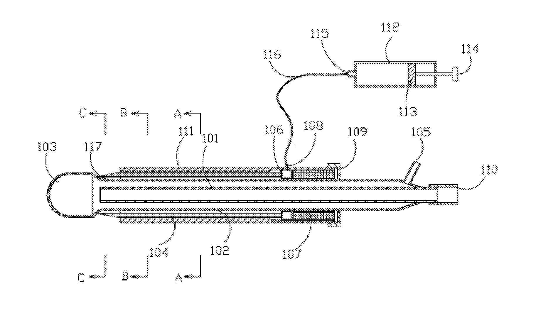
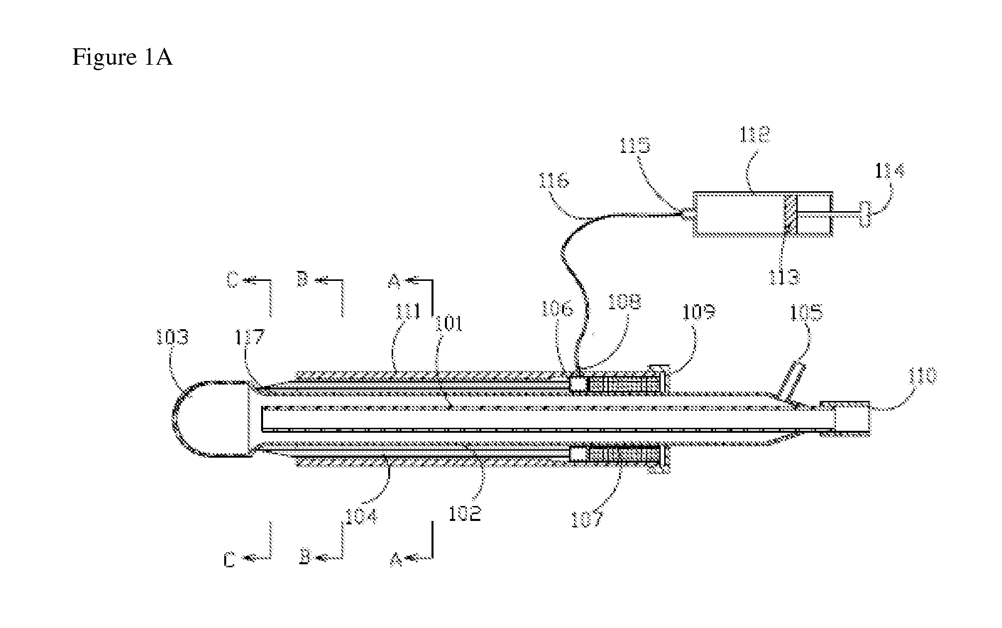
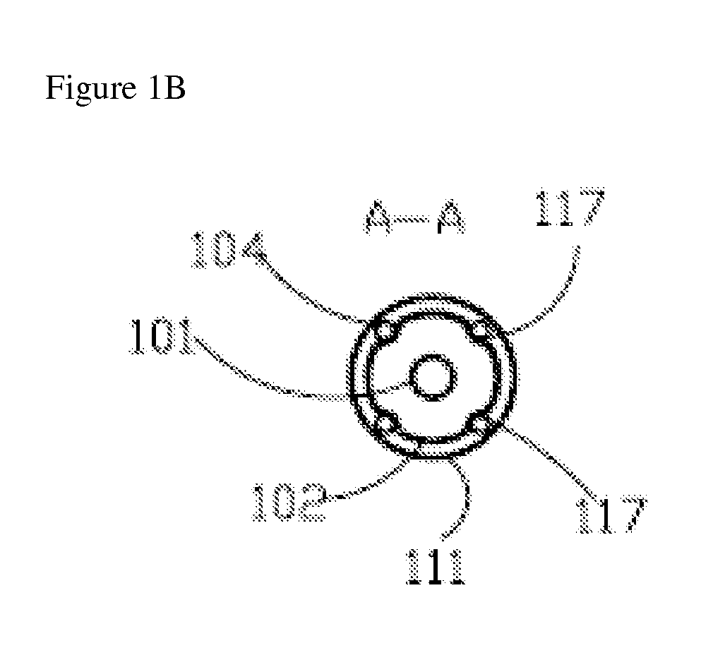
[0059]FIG. 1a, FIG. 1b, FIG. 1c and FIG. 1d show axial and transversal cross-sections of an illustrative cryoprobe 100 with a set of stationary adjacent needles.
[0060]Cryoprobe 100 preferably features a central supply lumen 101 with an inlet connection 110; a (preferably cylindrical) longitudinal shaft 102, which is provided with longitudinal grooves 117 diminishing to a zero or near zero dimension at their distal sections; and a cryotip 103. Central supply lumen 101 and longitudinal shaft 102 are preferably located within an external shaft 111.
[0061]A chamber 106, which is optionally annular, is preferably located within external shaft 111, adjacent to longitudinal shaft 102. Chamber 106 is for receiving an agent or agents to be administered to the site of cryotherapy. Chamber 106 features an inlet connection 108 and a (preferably annular) insert 107 for determining the position of chamber 106.
[0062]A ...
PUM
 Abstract
Description
Claims
Application Information