
Method And System For Encoding And Decoding Information With Modulation Constraints And Error Control

a modulation constraint and information technology, applied in the field of encoding and/or decoding information, can solve the problems of reducing unable to design constrained parity-check codes with minimum code-rate loss, and incurred code rate loss, so as to facilitate significantly simpler hardware implementation of encoder/decoder, simplify error correction, and reduce the number of parity-check bits

Inactive Publication Date: 2008-06-12
AGENCY FOR SCI TECH & RES
View PDF6 Cites 17 Cited by
  • Summary
  • Abstract
  • Description
  • Claims
  • Application Information

AI Technical Summary

Benefits of technology

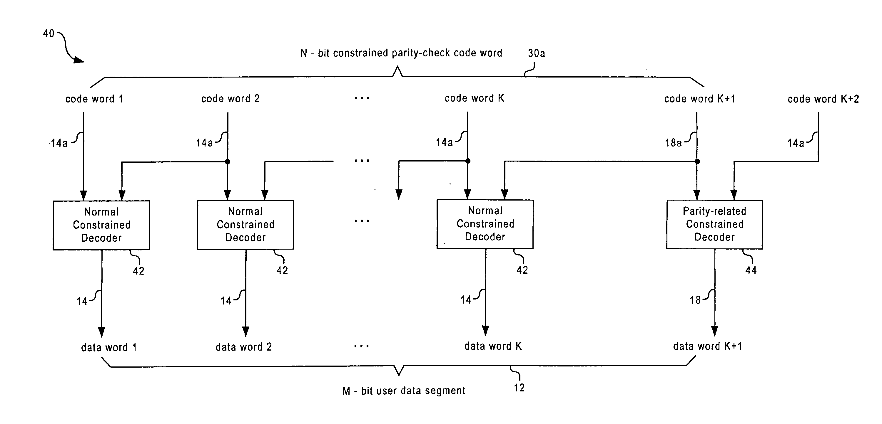
[0030]The present invention is able to provide a general and systematic way for constructing efficient constrained parity-check codes, for instance for optical recording systems. According to embodiments of the present invention, a constrained parity-check code includes two types of component codes: the normal constrained code and the parity-related constrained code, which are all designed to have the rates close to the Shannon capacity. The parity-check constraint over the entire code word is realised by concatenating the normal constrained code words with a specific parity-related constrained code word chosen from a candidate code word set. Both the component codes are finite-state codes with fixed lengths, which are designed based on the same FSM. This enables them to be concatenated in any order without violating the modulation constraints, and also facilitates significantly simpler hardware implementation of the encoder / decoder. The parity-check constraint is defined by the parity-check polynomial or parity-check matrix of a systematic linear block code. This provides a systematic way for defining the error detection criterion of the constraint parity-check codes. As a result, the codes constructed can detect any type of dominant error event as well as error event combinations of the system.
[0031]Preferred first and second embodiments of the present invention provide methods to design a code in the non-return-to-zero inverted (NRZI) format and the non-return-to-zero (NRZ) format, respectively. Designing the codes in NRZ format may reduce the number of parity-check bits required for error detection and simplify error correction (or post-processing). As will be appreciated, the parity-check codes used can be any linear block codes in the systematic form. The modulation constraint adopted can be any d constraint (d=1 and d=2). The new codes designed do not suffer from the error propagation between the parity-related constrained code word and the normal constrained code words, since the parity-related constrained code word is also protected by parity-check. Furthermore, stricter k constraint and the maximum transition run (MTR) constraint can also be added in the designed codes, by increasing the length of the code word, or the number of states of the FSM.

Problems solved by technology

As a result, a certain code rate loss will be incurred.
Although many attempts have been made by researchers in recent years to combine a constrained code with a parity-check code efficiently, the systematic design of constrained parity-check codes with minimum code-rate loss remains an open problem.
It is especially difficult to design constrained parity-check codes that satisfy multiple-bit parity-check constraints for optical recording systems.
However, it still has general losses, since only specific mixed-type errors for the magnetic recording system can be corrected.
Furthermore, its coding efficiency is low.
However, the concatenated coding scheme has two drawbacks: (i) during decoding, local demodulation is needed to derive the parity-checks.
Obviously, this will increase the decoding complexity.
Therefore, errors occurring in the parity-related data block may lead to further errors during the decoding of the whole data block.
Thus results in error propagation.
First, the combi-code scheme is designed to correct a specific type of error event (i.e. single-bit transition shift error, or n-bit transition shift errors in the same direction). It is difficult to generalise the scheme to detect an arbitrary type of error event as well as error event combinations.
Second, the combi-code scheme achieves high efficiency only for d=2 codes. For d=1 codes that are used in third generation optical recording systems, highly efficient combi-codes are not available. (cf. above) proposed that high efficiency d=1 codes can be obtained by either (i) using a sophisticated time-varying encoder, or (ii) combining parity-check enabling codes with dc-free enabling codes. The disadvantage of a time-varying encoder is that, for each phase of the encoder, a separate code is required. This will cause significant increases in the implementation complexity. On the other hand, the combination of parity-check enabling codes with dc-free enabling codes will weaken the dc-suppression. This is because, to get a satisfactory dc-suppression, dc-free enabling codes need to be inserted more frequently than the parity-check enabling codes.
Third, the main component code (i.e. the standard code) used by the combi-code scheme is still a rate 2 / 3 (1,7) code for d=1 constraint, and a rate 8 / 15 (2,10) code for d=2 constraint. The efficiency of both the standard codes and the parity-check enabling codes could be further improved by using the state splitting method proposed by Immink et al.

Method used


Image

  • Method And System For Encoding And Decoding Information With Modulation Constraints And Error Control
  • Method And System For Encoding And Decoding Information With Modulation Constraints And Error Control
  • Method And System For Encoding And Decoding Information With Modulation Constraints And Error Control

Examples


first embodiment

2. Code Design Method

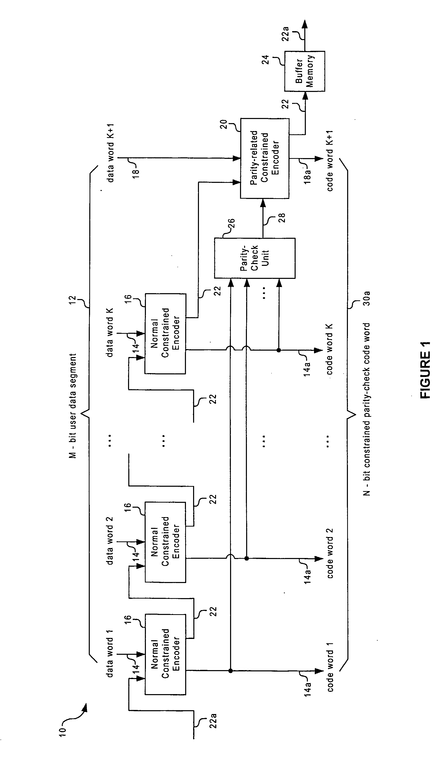
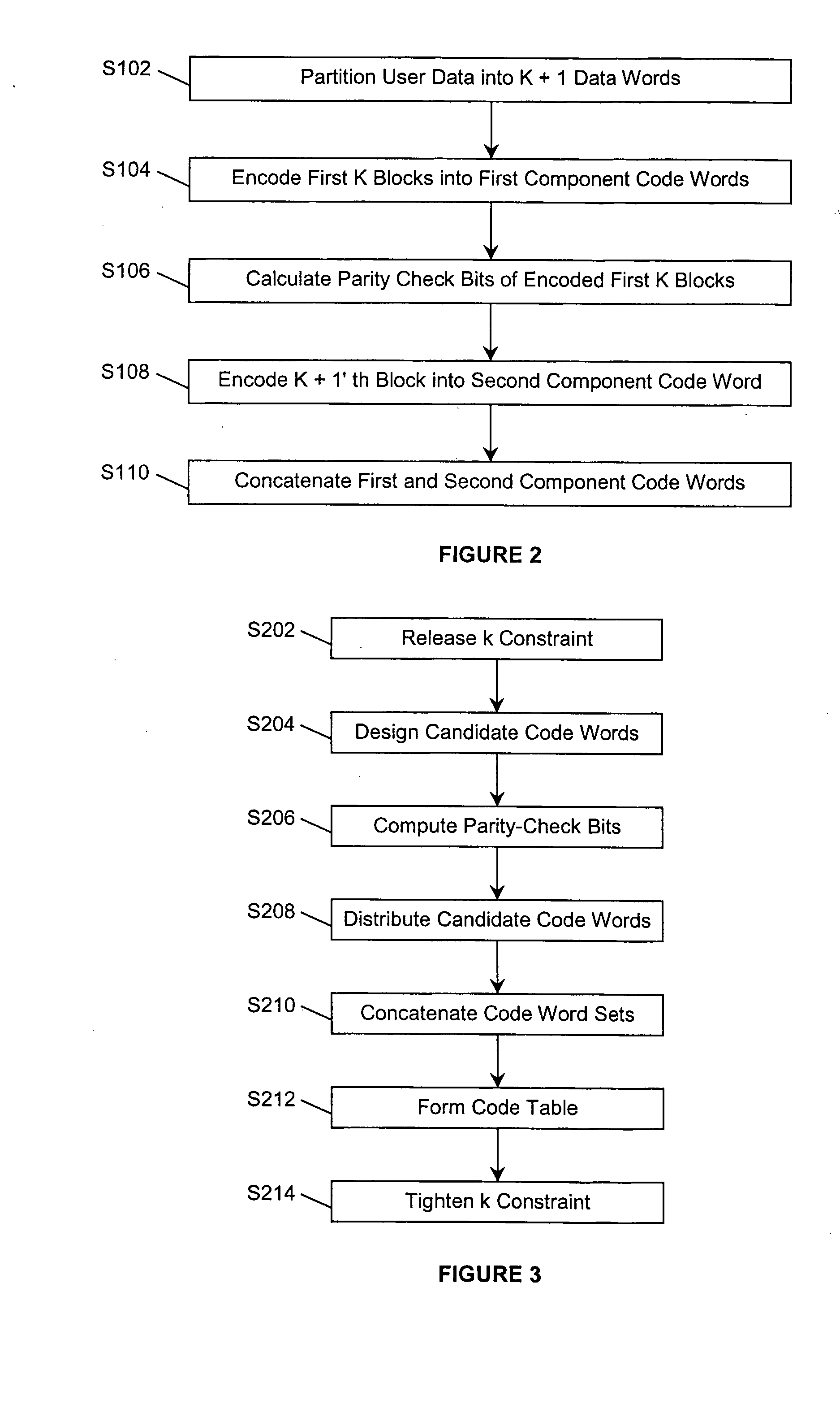
[0059]In a first preferred embodiment, the codes are designed in NRZI format. FIG. 1 is a schematic block diagram of encoding apparatus according to a first embodiment of the invention, in the form of a constrained parity-check encoder 10, which may, for example, operate according to the process illustrated in the flowchart of FIG. 2. As illustrated, an M-bit segment of user data 12 is partitioned into K+1 data words (step S102). Among these data words, the K leading data words 14 are individually encoded into first component code words (step S104) by normal constrained encoders 16. At the encoder outputs, K normal constrained code words 14a are obtained. The K+1'th data word 18 is encoded into a second component code word (step S108), which is denoted as the parity-related constrained code word 18a, by a parity-related constrained encoder 20. During encoding the data words into the two component code words 14a and 18a, following state information 22, for instan...

second embodiment

3. Code Design Method

[0083]In the above description of the code design, the coded bits are all defined in NRZI format. The present invention further proposes an approach to design the code in NRZ format. It may be preferable to encode the data in NRZ format due to the following reasons.

[0084]On the one hand, by making use of the parity-check results of the detected sequence of constrained parity-check code words as well as the channel side information, errors occurring in the output sequences of the channel detector can be corrected. The process of inverse preceding may propagate errors in the channel detected data sequence and enlarge the length of error events. This will cause an increase in the number of parity-check bits that are required for detecting errors.

[0085]On the other hand, carrying out error correction or post-processing for the constrained parity-check codes at the output of the channel detector is simpler and more straightforward than doing it at the output of the i...


PUM


Abstract

A method and system for encoding a segment of user data words into a segment of code words so that both modulation constraints and a predetermined parity-check constraint are satisfied. Each segment of the user data is partitioned into several data words, and encoded separately by first and second types of component code, which are referred to as the normal constrained code and the parity-related constrained code, respectively. The parity-check constraint over the combined code word is achieved by concatenating the sequence of normal constrained code words with a specific parity-related constrained code word chosen from a candidate code word set. Both the component codes are finite-state constrained codes, which are designed to have rates close to the Shannon capacity. Furthermore, they are based on the same finite state machine (FSM), which enables them to be connected seamlessly, without violating the modulation constraints. Two preferred embodiments are provided to design a code in the non-return-to-zero inverted (NRZI) format and the non-return-to-zero (NRZ) format, respectively. Designing the codes in NRZ format may reduce the number of parity-check bits required for error detection and simplify error correction or post-processing. The parity-check constraint is defined by the parity-check polynomial or parity-check matrix of a systematic linear block code, which could detect any type of dominant error event as well as error event combinations of a given optical recording system. As a result, the information density of the system is improved.

Description

BACKGROUND OF THE INVENTION[0001]1. Field of the Invention[0002]The present invention relates to encoding and / or decoding information, for instance in optical recording systems. More particularly, the invention provides a method and system of coding information with improved information density, by imposing both modulation constraints and parity-check constraints in channel coded data sequences.[0003]2. Description of the Related Art[0004]Modulation codes, also known as constrained codes, are used in recording systems to translate an arbitrary sequence of user data into a sequence with special properties required by the relevant systems. Two major constraints for optical recording systems are run-length constraints, or (d, k) constraints, and the dc-free constraint. The runlength constraints bound the minimal and / or maximal lengths of runs of zeros in an encoded data stream, to mitigate the problems of intersymbol interference and inaccurate timing. The dc-free constraint avoids int...

Claims


Application Information

Patent Timeline
Patent Type & Authority Applications(United States)
IPC IPC(8): H03M13/13G06F11/10
CPCG11B20/10296G11B20/1833G11B2020/1288H03M13/31H03M5/145H03M13/11G11B2220/2541
Inventor CAI, KUIIMMINK, KEES A. SCHOUHAMER
Owner AGENCY FOR SCI TECH & RES
Learn More