
Apparatuses and methods for controlling the temperature of glass forming materials in forehearths

a technology of glass fiber forming apparatus and temperature control, which is applied in the direction of lighting and heating apparatus, manufacturing tools, furniture, etc., can solve the problems of reducing the residence time and the volume of molten glass, and achieve uniform or substantially uniform chemical and physical properties of glass fibers, reduce shear break rate, and more homogeneous viscosity

Inactive Publication Date: 2008-06-19
OCV INTELLECTUAL CAPITAL LLC
View PDF34 Cites 17 Cited by
  • Summary
  • Abstract
  • Description
  • Claims
  • Application Information

AI Technical Summary

Benefits of technology

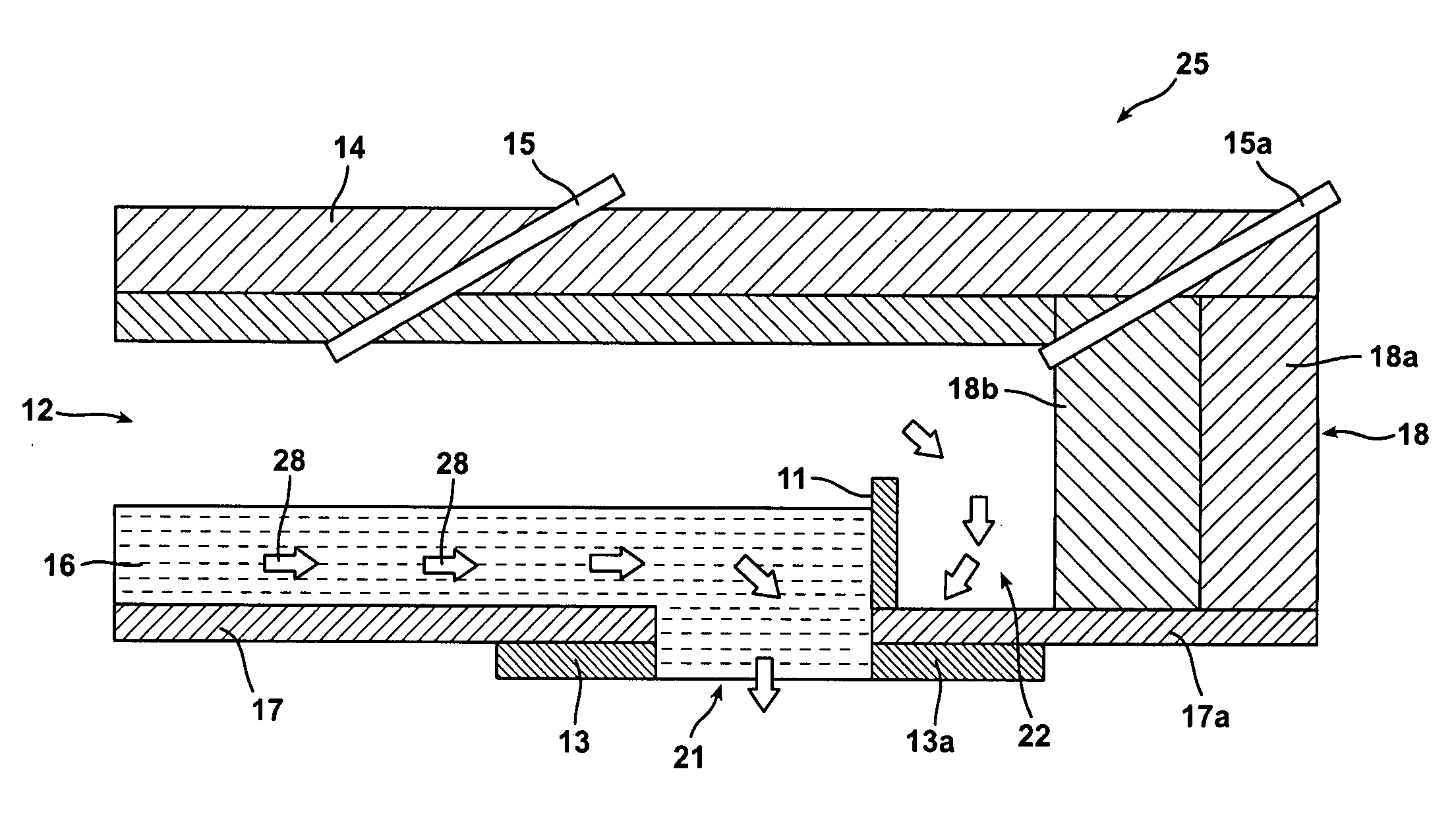
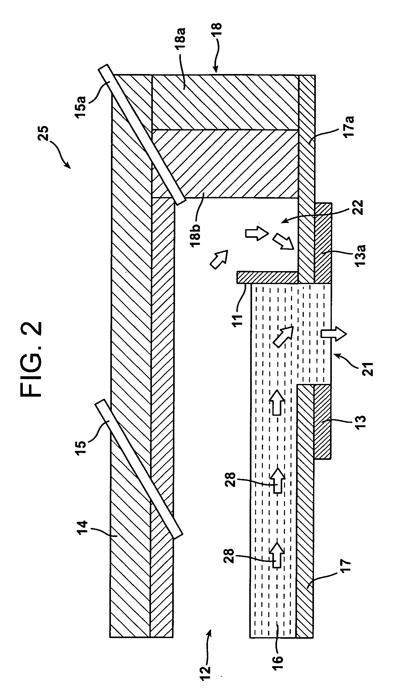
[0015]It is an advantage of the present invention that uniform or substantially uniform chemical and physical properties of the glass fibers may be obtained by reducing the temperature gradient across the end position.
[0016]It is another advantage of the present invention that a decrease in shear break rate occurs when there is a uniform or substantially uniform temperature of the molten glass material across the end position.
[0017]It is a further advantage of the present invention that the molten glass flowing through the end position and into the bushing has a more homogenous viscosity when there is little or no temperature gradient of the molten glass material across the end position. As a result, a more homogenous glass fiber and glass product may be formed.
[0018]It is yet another advantage of the present invention that there is no need for an additional energy source or a control system infrastructure when a gas cavity is employed within the forehearth between the glass contact wall and the end wall.
[0019]It is also an advantage of the present invention that the heating element permits for the control and custom tailoring of the particular thermal requirements of a given installation.
[0020]It is a feature of the present invention that the inventive forehearths provide a substantially homogeneous temperature to molten glass forming materials across the end position of the forehearths.

Problems solved by technology

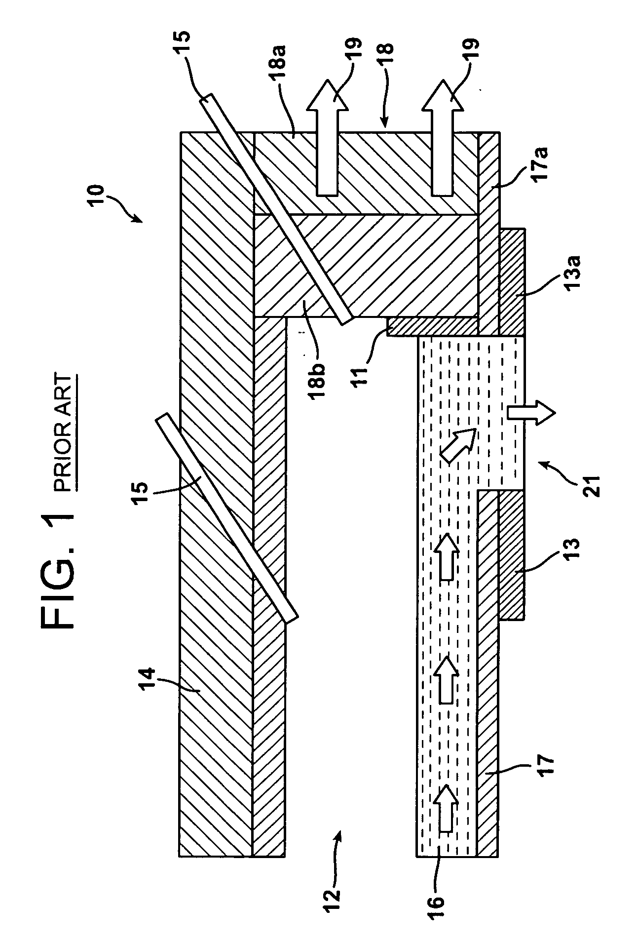
Additionally, the refractory block decreases the residence time and the volume of molten glass over the end position.

Method used


Image

  • Apparatuses and methods for controlling the temperature of glass forming materials in forehearths
  • Apparatuses and methods for controlling the temperature of glass forming materials in forehearths
  • Apparatuses and methods for controlling the temperature of glass forming materials in forehearths

Examples


Embodiment Construction

[0028]Unless defined otherwise, all technical and scientific terms used herein have the same meaning as commonly understood by one of ordinary skill in the art to which the invention belongs. Although any methods and materials similar or equivalent to those described herein can be used in the practice or testing of the present invention, the preferred methods and materials are described herein. All references cited herein, including published or corresponding U.S. or foreign patent applications, issued U.S. or foreign patents, and any other references, are each incorporated by reference in their entireties, including all data, tables, figures, and text presented in the cited references.

[0029]In the drawings, the thickness of the lines, layers, and regions may be exaggerated for clarity. It is to be noted that like numbers found throughout the figures denote like elements. It will be understood that when an element is referred to as being “on,” another element, it can be directly on ...


PUM

PropertyMeasurementUnit
Temperatureaaaaaaaaaa
Distanceaaaaaaaaaa
Distanceaaaaaaaaaa

Abstract

Forehearths that create a substantially homogeneous temperature to molten glass forming materials across the end position are provided. A gas cavity, a weir, a refractory block, or a heating element in the forehearth may be utilized to reduce a temperature gradient of molten glass forming materials across the end position. Reducing the temperature difference of the molten glass forming material across the end position permits for improved chemical and physical properties of the glass fibers and the end products formed from the glass fibers. In addition, a reduction in the temperature gradient across the end position produces a more homogenous glass fiber and glass product. Further, a reduction in the shear break rate occurs when the molten glass forming material has a temperature that is substantially the same across the end position, which results in a reduction in the breakage of glass fibers and an increase in manufacturing efficiency.

Description

TECHNICAL FIELD AND INDUSTRIAL APPLICABILITY OF THE INVENTION[0001]The present invention relates generally to a forehearth in a glass fiber forming apparatus, and more particularly, to a forehearth that provides a substantially homogeneous temperature to molten glass forming materials across the end position of the forehearth.BACKGROUND OF THE INVENTION[0002]In forming glass fibers, a glass forming material is heated in a glass melting furnace until the glass forming material is degraded to a molten state. The molten glass is passed from the glass melting furnace and into a forehearth linking the glass melting furnace and a glass forming machine. As the molten glass flows through the forehearth, it passes downwardly through openings that are positioned in a spaced relation along the bottom of the forehearth and into a bushing. Glass streams are then attenuated through orifices located in the bushing and formed into glass filaments or fibers by methods known to those of skill in the ...

Claims


Application Information

Patent Timeline
IPC IPC(8): C03B7/06C03B7/07
CPCC03B5/182C03B7/07C03B7/06C03B7/02
Inventor ADAMS, HARRYPURNODE, BRUNO A.BEMIS, BYRONPRESCOTT, PATRICK J.STREICHER, WILLIAM L.BAKER, DAVID J.
Owner OCV INTELLECTUAL CAPITAL LLC
Learn More