Small Vessel Capable Of High Tow Force

a small watercraft and high towing force technology, applied in the field of watercraft, can solve the problems of increasing the limitation of conventional small watercraft for towing high forces, unstable craft, and vessel instability, and achieve the effects of reducing the impact of towing force on the stability and resistance of watercraft, reducing the chafing, and reducing the chafing

Inactive Publication Date: 2008-06-19
BEIN THOMAS W
View PDF5 Cites 11 Cited by
  • Summary
  • Abstract
  • Description
  • Claims
  • Application Information

AI Technical Summary

Benefits of technology

[0009]The hull is shaped to develop minimal resistance when moving through the water. There is a vertical slot formed through the hull at the transom along the centerline of the craft extending from the top of the aft deck area to the hull plating. The slot is positioned so that a tow cable can pass through the slot when the angle of the tow cable is below horizontal. Conventional winches and reels are utilized to deploy and recover the tow cable. Wear resistant material is attached to the lower and aft edges of the slot thru the hull to eliminate chafing between the cable and the watertight hull boundary.
[0010]When the watercraft is operating with the tow cable deployed, with calm seas, with no currents, and with a tow cable angle below horizontal the tow cable will extend through the slot in the hull. The force on the tow cable will exert both a longitudinal and a vertical force on the craft. The impact to the stability and resistance of the watercraft due to the tow forces is reduced in the present invention because it permits the forces on the tow cable to be reacted closer to the center of gravity of the watercraft.
[0011]When a cross current is added to the operating conditions above, the watercraft will need to operate at a angle, referred to as yaw angle, to the desired

Problems solved by technology

When the tow force is large compared to the force required to push the watercraft through the water, the location where the tow force is applied to the craft can cause the vessel to become unstable.
The limitation of conventional small watercraft for

Method used


Image

  • Small Vessel Capable Of High Tow Force
  • Small Vessel Capable Of High Tow Force
  • Small Vessel Capable Of High Tow Force

Examples


Embodiment Construction

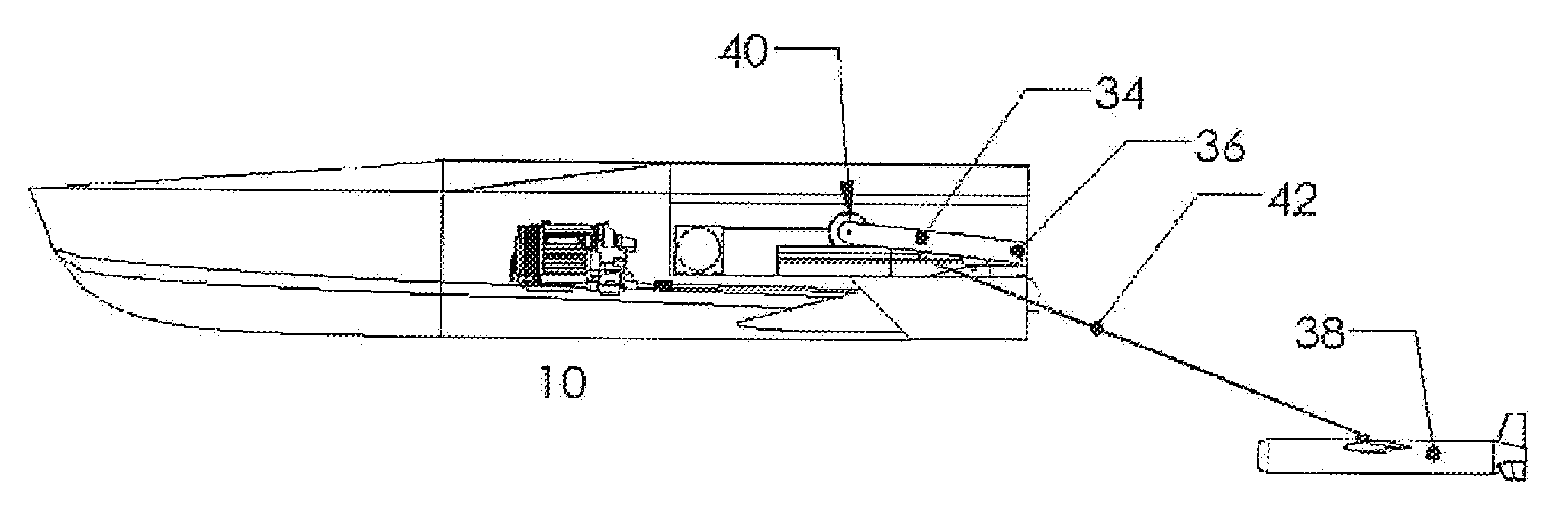
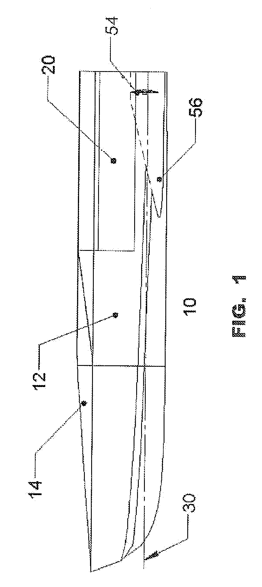
[0025]Referring now to the drawings wherein like characters designate like or corresponding parts throughout the several views. A semi-planning hull is shown in all of the implementations to simplify the figures. The present invention can be readily applied to other hull forms or shapes. FIG. 1 shows a side view of the watercraft 10 with payload mounting area 20 empty. The hull plating 12 is joined to the deck plating 14 to form a watertight boundary to prevent water from entering the craft in the event of a wave washing over the deck or the craft capsizing due to large wave impact. The design waterline is indicated by 30. The propellers 54 are recessed in tunnels 56 to protect them from damage due to impacting objects in the water.

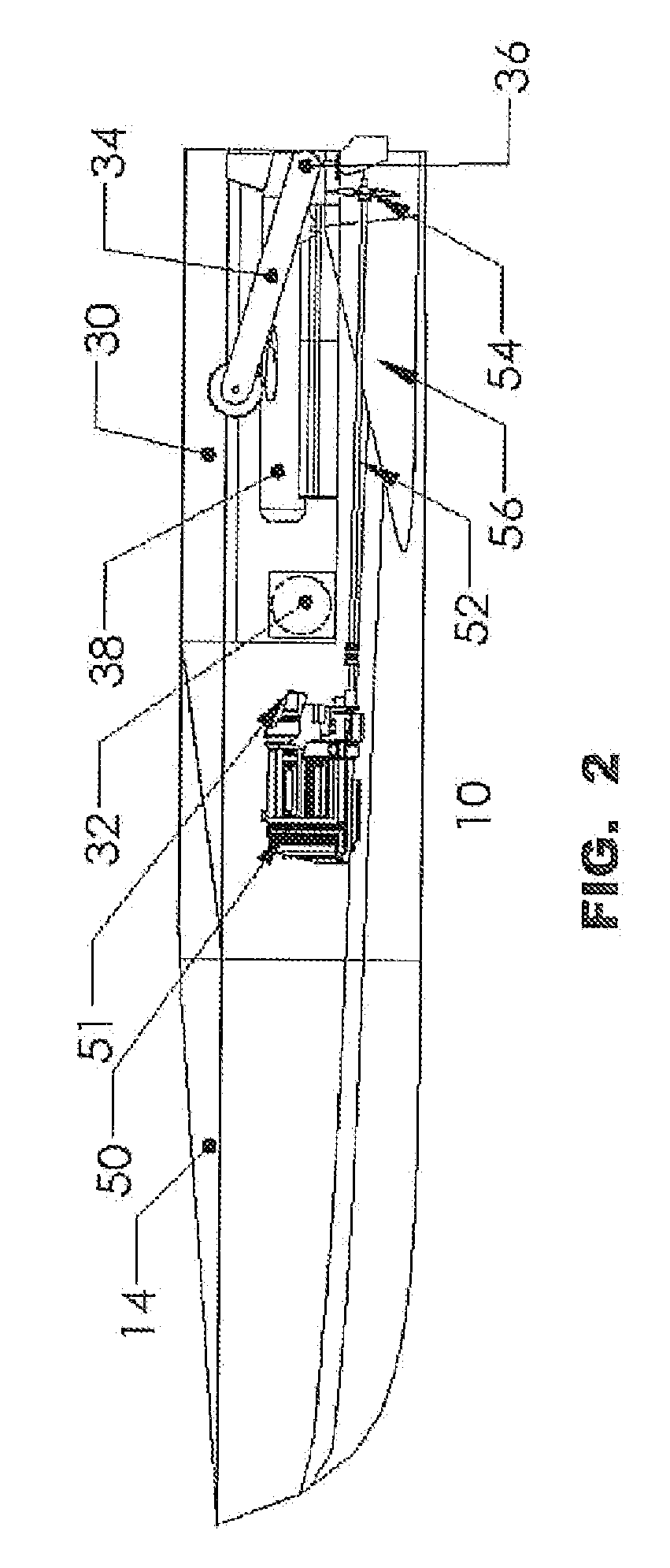
[0026]FIG. 2 is a section view showing the arrangement of the major components. The engines 50 are located forward of the payload area as close to the hull plating as possible. The engine exhaust 51 discharges through the side of the hull. The drive shaft...


PUM


Abstract

A small watercraft with watertight hull and an area at the rear in close proximity to the waterline that provides a means to mount payloads. Engines powering propellers are installed forward of the payload area and are covered by a water-tight deck with openings for intake air. Ancillary systems to support the engines and electrical components are provided in a conventional manner. A feature of the present invention is that the hull has been modified to permit a tow cable to pass through the hull from a towing winch to a towed body. The present invention moves the reaction from the tow force forward of the craft transom and low in the hull which greatly improves the stability of the small vessel particularly when it is operating in rough water. The present invention is applicable to any size of the hull and any materials that the hull is fabricated from.

Description

CROSS REFERENCE TO RELATED APPLICATIONS[0001]Not ApplicableSTATEMENT REGARDING FEDERALLY SPONSORED RESEARCH[0002]Not ApplicableREFERENCE TO SEQUENCE LISTING[0003]Not ApplicableBACKGROUND OF THE INVENTION[0004]This invention relates generally to a watercraft which is used for towing objects at or below the surface of the water. The power to propel the craft through the water is the total of the resistance of pushing the hull through the water plus the tow force. The tow force exerted by conventional watercraft is small compared to the force required to push the hull through the water.[0005]When the tow force is large compared to the force required to push the watercraft through the water, the location where the tow force is applied to the craft can cause the vessel to become unstable. Specific provisions are made to maintain the stability of the vessel. For example, commercial tugboats attach the tow cable as close to the center of gravity of the vessel as possible. The center of gra...

Claims


Application Information

Patent Timeline
IPC IPC(8): B63B1/00
CPCB63B35/68B63B21/66
Inventor BEIN, THOMAS W.
Owner BEIN THOMAS W
Why Eureka
Try Eureka