
Display device having multi-touch recognizing function and driving method thereof

a multi-touch recognition and display device technology, applied in the field of display devices, can solve the problems of multi-touch recognition devices wrongly recognizing touch locations, touch panel malfunctions, related art has no way of compensating the distortion generated in the lens itself in multi-touch recognition devices, etc., and achieves strong structural stability for the touch recognition system

Active Publication Date: 2008-06-19
LG DISPLAY CO LTD
View PDF5 Cites 97 Cited by
  • Summary
  • Abstract
  • Description
  • Claims
  • Application Information

AI Technical Summary

Benefits of technology

[0011]An object of the present invention to provide a display device having multi-touch recognizing function that obtain a strong structural stability for the touch recognition system.
[0012]Another object of the present invention to provide a display device having multi-touch recognizing function that maintains an appearance of the display device.

Problems solved by technology

However, if a multi-touch is generated by two or more substantially simultaneous contact points, the touch panel might malfunction or any one of the touches can be selected by a pre-set program.
The multi-touch recognition device might wrongly recognize a touch location due to the aberration of lens and the like in case of using a camera having lens.
Further, the multi-touch recognition device might have the location of the camera optically misaligned against the touch surface.
However, the related art has no way of compensating the distortion generated in the lens itself in the multi-touch recognition device.
Further, the multi-touch recognition device has a problem in that a touch recognition circuit is separated from a drive circuit of the display device such that the display action and the touch recognition action are not synchronized, thereby realizing the circuit inefficiently.
Although there is a method of embedding an optical sensor of the multi-touch recognition device in each pixel of the display device, but this method has another problem in that the aperture ratio of the display device is decreased to lower the brightness thereof due to the optical sensor.

Method used


Image

  • Display device having multi-touch recognizing function and driving method thereof
  • Display device having multi-touch recognizing function and driving method thereof
  • Display device having multi-touch recognizing function and driving method thereof

Examples


first embodiment

[0068]A lens distortion compensation method according to the present invention will be explained in conjunction with FIGS. 9 to 11. In the lens of the cameras 21A to 21D, if the angle of view is 90°, the distortion by the lens aberration satisfies a bilateral symmetry on the basis of a reference line Lref pertinent to 45° by the lens characteristic, as in FIG. 9.

[0069]FIG. 10 schematically represents a distortion model of the lens exemplified in the right surface of the reference line. If the camera 21A faces an effective touch location ‘A’, the measurement angle of the effective touch location where the actual touch is made should be ‘θ’, but the camera 21A recognizes the effective touch point as ‘A’ located in the mis-recognized measurement angle ‘θ’ because of the lens aberration. Accordingly, the measurement angle where the lens aberration is not compensated includes an error of as much as “θ−θ′”. In order to compensate the error of the measurement angle, the multi-touch signal ...

second embodiment

[0078]FIG. 18 is an example representing an angle error between a calculated value and a measured value. In FIG. 18, x-axis is a calculated value for N touch points, and y axis is an angle error for N touch points. In order to make an angle error curve more accurate and to obtain an accurate angle error value as in FIG. 18, the lens distortion compensation method according to the present invention performs a polynomial curve fitting in use of a third-order or higher-order polynomial expression as in Mathematical Formula 4. (S105)

[Mathematical Formula 4]

y=a0+a1x+a2x2+a3x3  (1)

y=xa  (2)

â=(xTx)−1xTy  (3)

[0079]Herein, ‘x’ is an angle calculation value (N×4 matrix) for each touch point, ‘y’ is an error value (N×1 matrix) between the measurement value and the calculation value for each touch point, and ‘a’ is a third-order polynomial coefficient (4×1 matrix). (1) of Mathematical Formula 4 is a third-order polynomial expression for fitting a camera error curve, and (2) of Mathematical Form...


PUM


Abstract

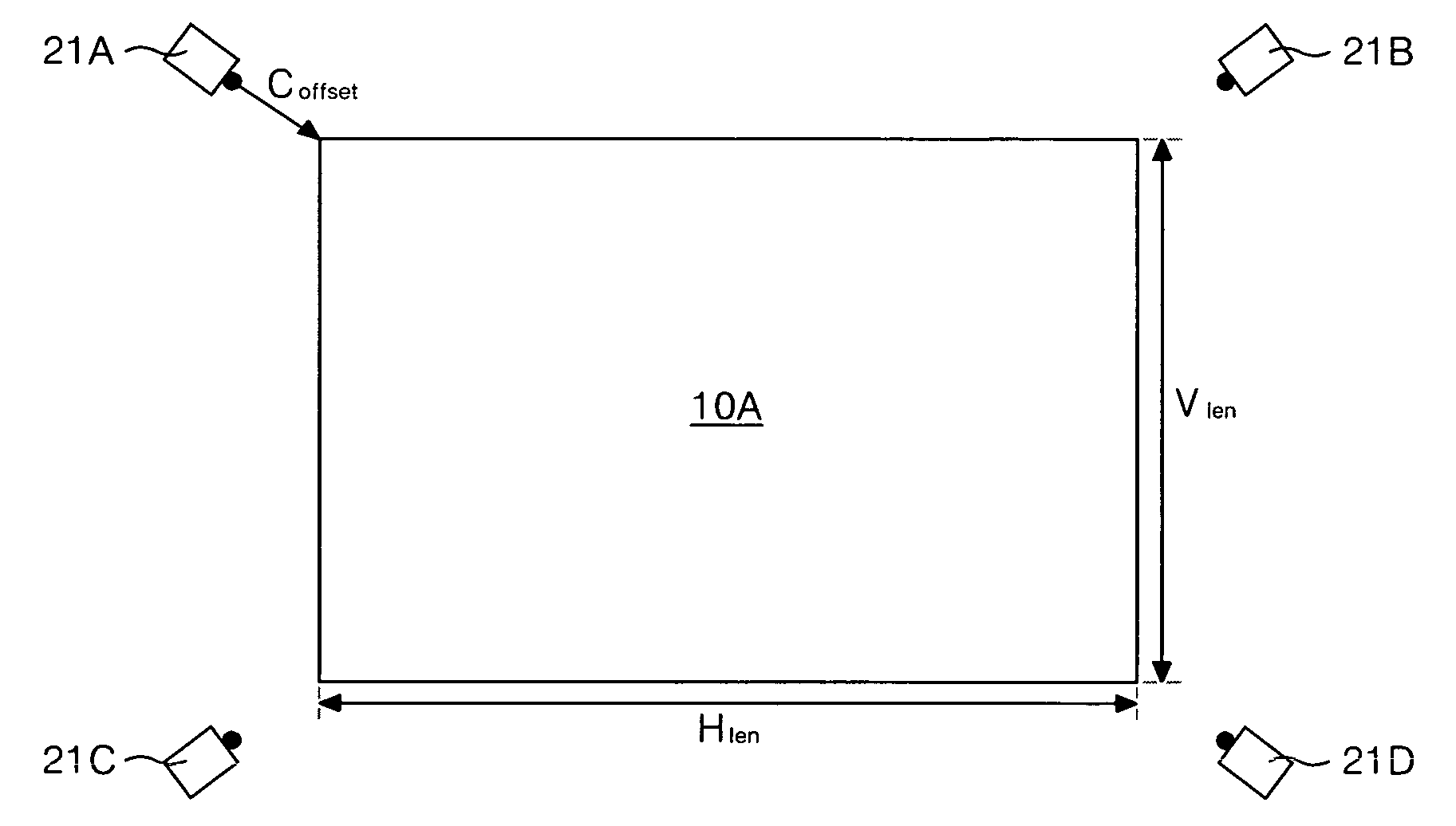
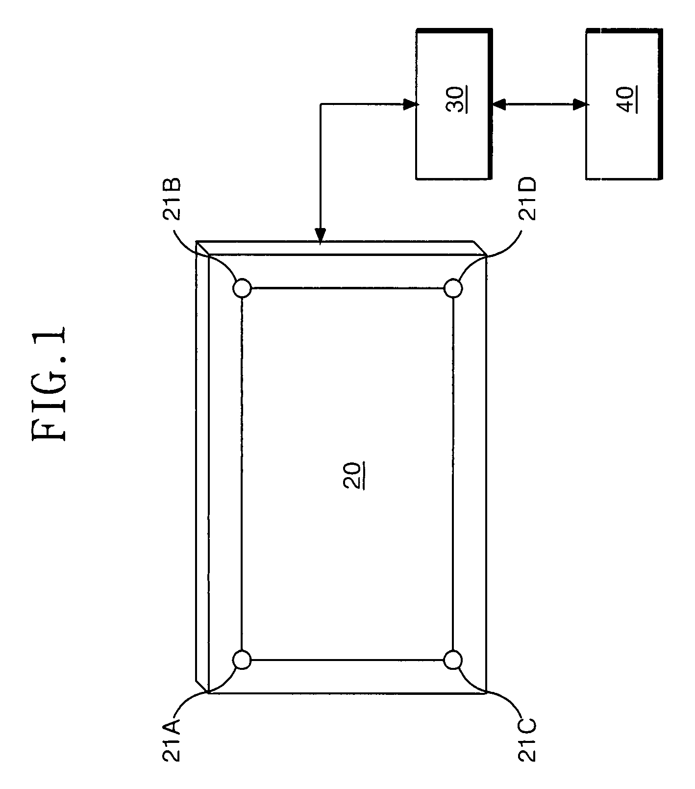
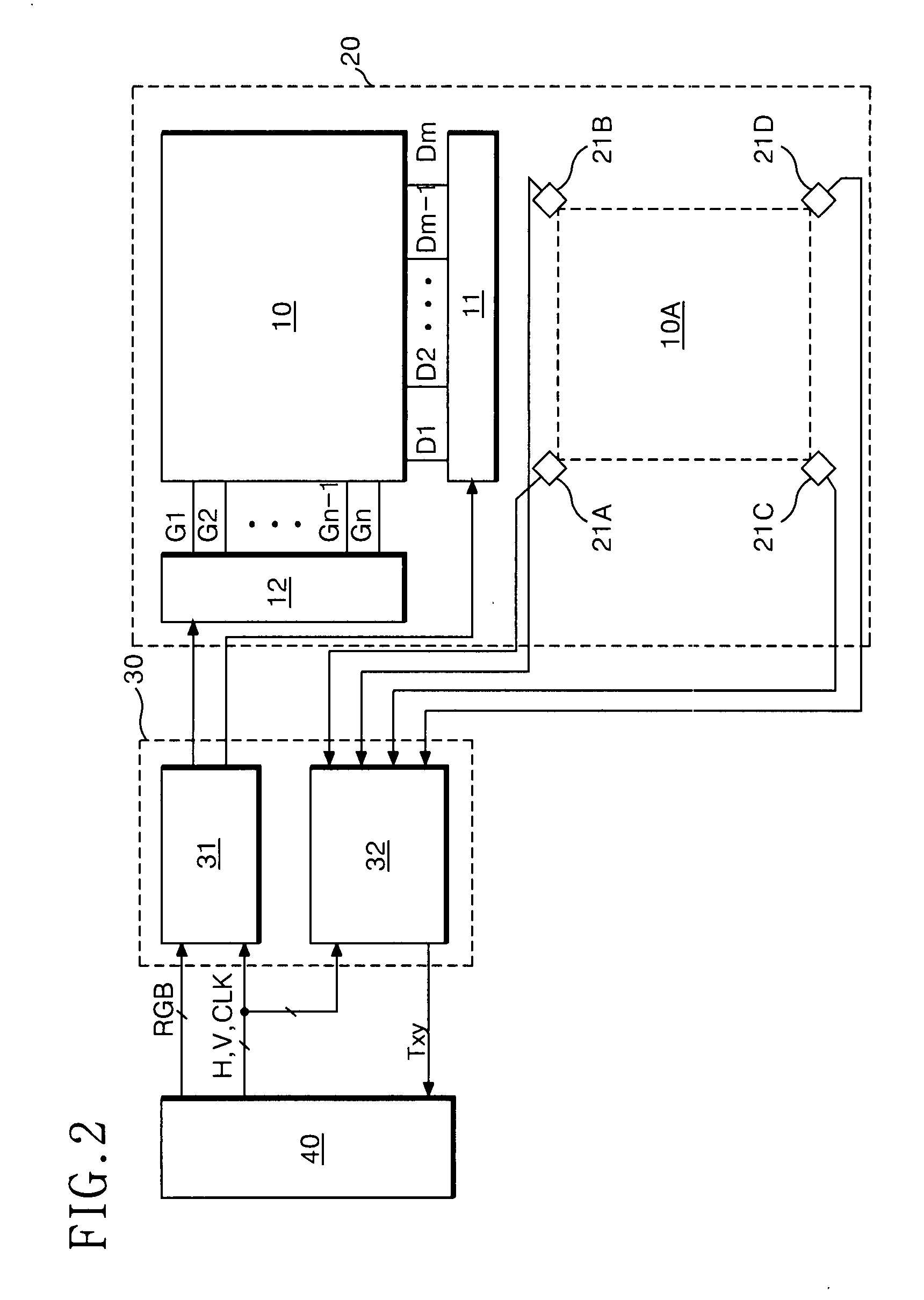
A display device having a multi-touch recognition function includes an integration module having a plurality of cameras integrated at an edge of a display panel; a look-up-table of a plurality of compensation angles in an range of about 0 to about 90 degrees corresponding to each of the plurality of cameras; and processor that detects a touch area using at least first and second images captured by the plurality of cameras, respectively, and compensates the detected touch area with one of the plurality of compensation angles.

Description

[0001]This application claims the benefit of the Korean Patent Application No. 10-2006-128529 filed on Dec. 15, 2006, and the Korean Patent Application No. 10-2007-024180 filed on Mar. 12, 2007, both of which are hereby incorporated by reference in their entirety.BACKGROUND OF THE INVENTION[0002]1. Field of the Invention[0003]Embodiments of the present invention relate to a display device, and more particularly to a display device and a driving method thereof. Embodiments of the present invention are suitable for a wide scope of applications. In particular, embodiments of the present invention are suitable for compensating a lens distortion in a multi-touch recognition for a display device.[0004]2. Description of the Related Art[0005]Generally, a touch panel is a type of user interface that is attached to a display device with the property that an electrical characteristic thereof is changed at a contact point where a hand or a pen touches the panel. Touch panels have been used in v...

Claims


Application Information

Patent Timeline
Patent Type & Authority Applications(United States)
IPC IPC(8): G06F3/042
CPCG06F3/0428
Inventor JANG, HYUNG UKBAE, SANG HYUCKSHIM, YEON SHIM
Owner LG DISPLAY CO LTD
Learn More