Transflective liquid crystal displays

a liquid crystal display and reflector technology, applied in non-linear optics, instruments, optics, etc., can solve the problems of increased power consumption, increased cost, and non-100% transmittance of polarizing layers, and achieve high contrast ratio and brightness. high

Inactive Publication Date: 2008-06-19
PANASONIC LIQUID CRYSTAL DISPLAY CO LTD +1
View PDF7 Cites 43 Cited by
  • Summary
  • Abstract
  • Description
  • Claims
  • Application Information

AI Technical Summary

Benefits of technology

[0012]It is therefore an object of the present invention, which has been devised to solve the problems above, to provide a transflective liquid crystal display with a wide viewing angle which is capable of obtaining a high contrast ratio in the transmissive display and the reflective display without causing increase in the driving voltage.
[0018]It is possible according to the present invention to implement a transflective liquid crystal display in which the transmissive display and the reflective display are achieved with high brightness and a high contrast ratio.

Problems solved by technology

This hence leads to a problem of increase in the power consumption.
There also appears a problem in which the cost becomes greater due to use of an expensive driver capable of appling such higher voltages.
In addition, the transmittance of the polarizing layer is not 100% even for linearly polarized light having a vibration plane in a direction perpendicular to the absorption axis.
It is hence feared that the polarizing layer is deteriorated in its optical property.

Method used


Image

  • Transflective liquid crystal displays
  • Transflective liquid crystal displays
  • Transflective liquid crystal displays

Examples


embodiment 1

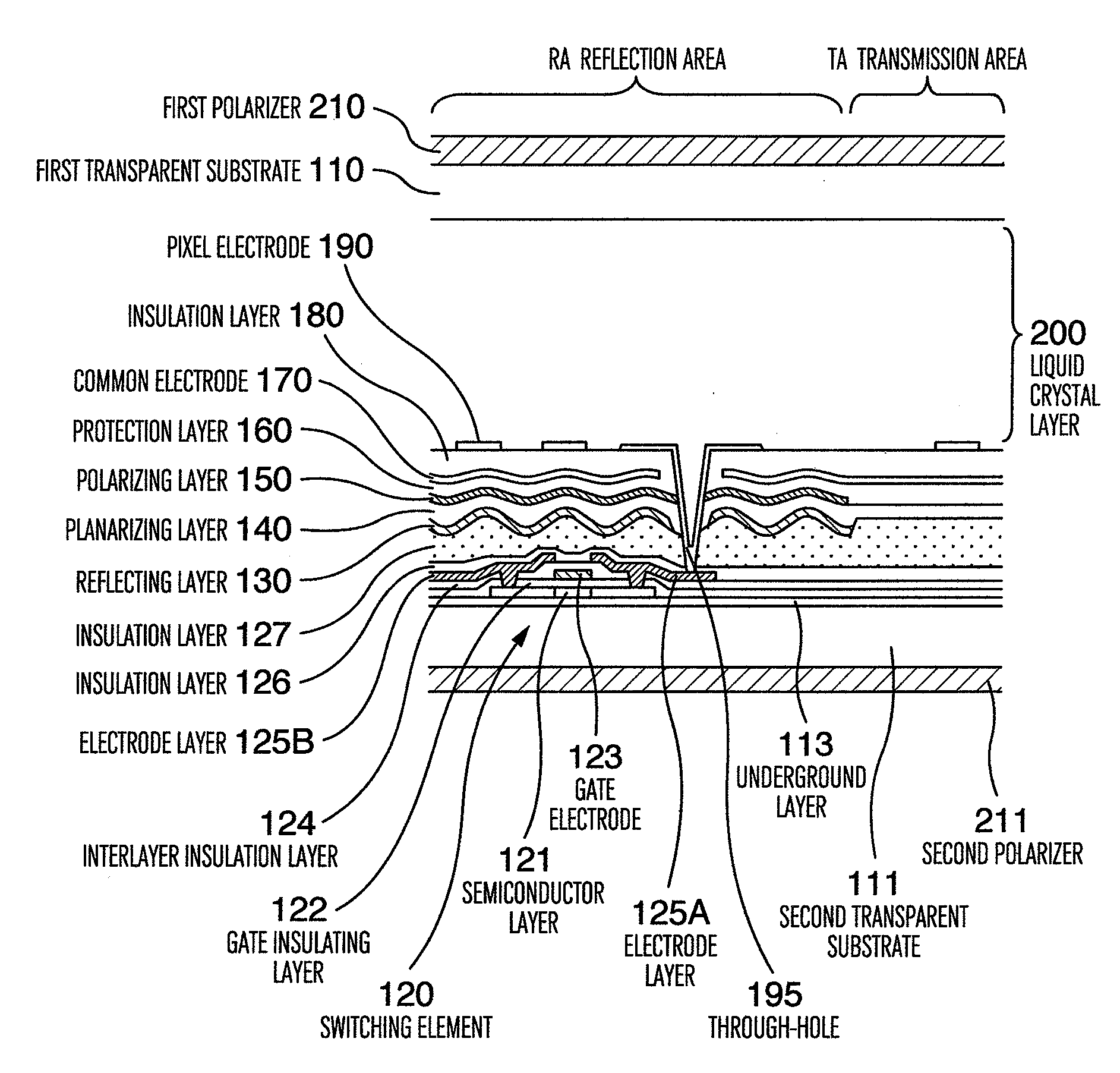
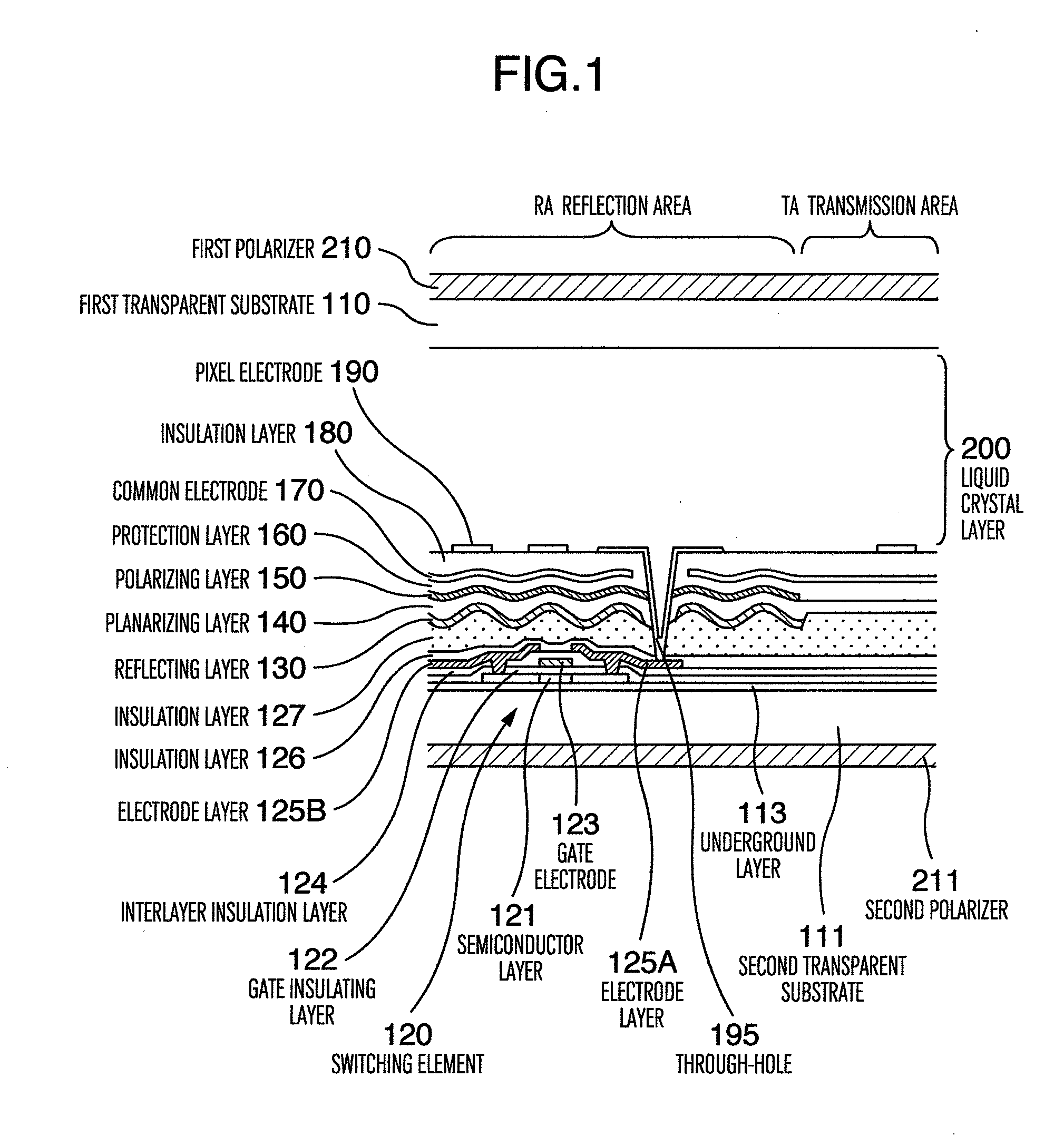
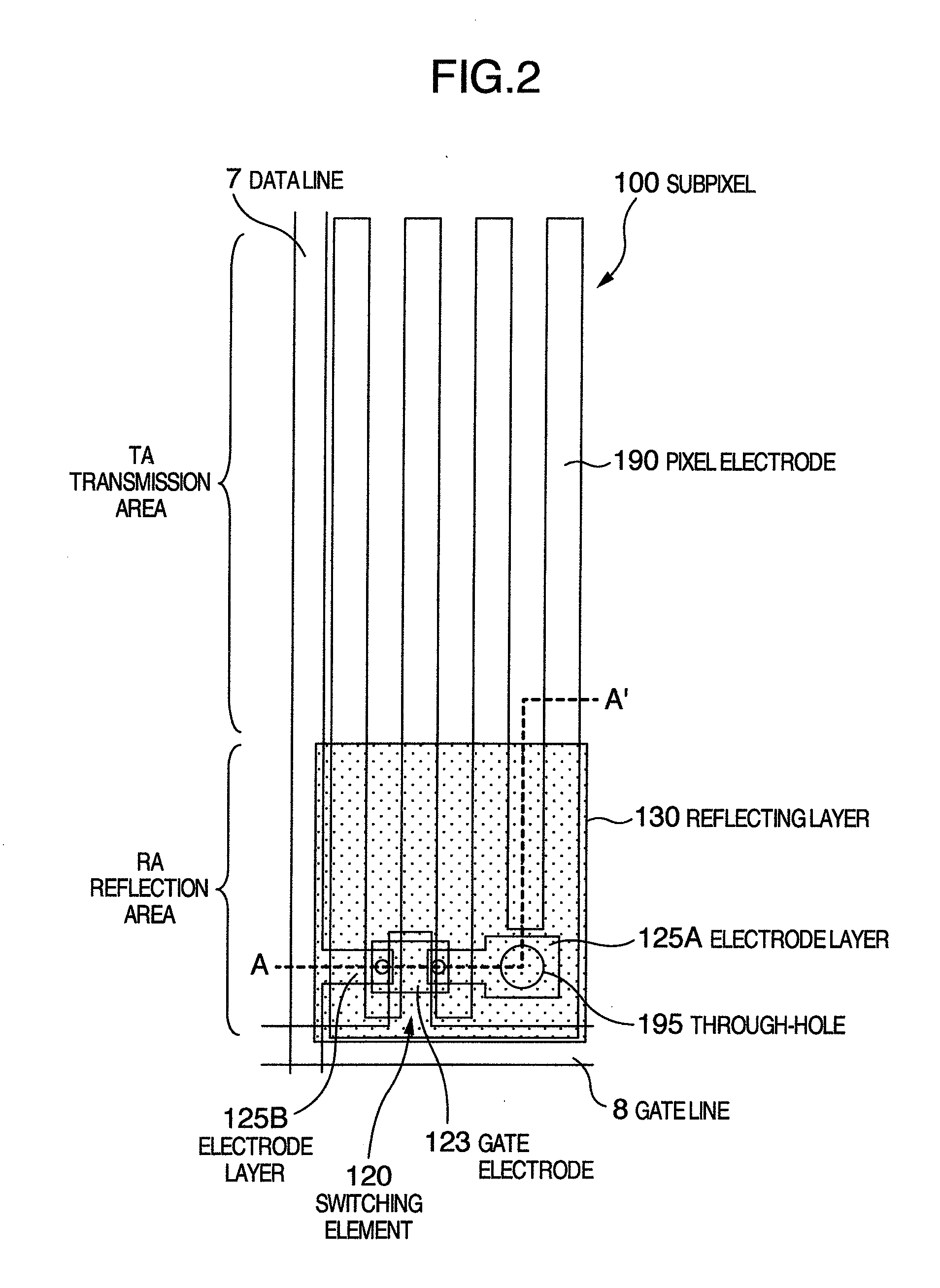
[0037]FIG. 1 shows a general configuration in a cross-sectional view of a primary section of a subpixel 100 used in a liquid crystal display panel 1 of a transflective liquid crystal display according to the present invention. FIG. 2 shows a general configuration in a plan view of a primary section of the subpixel 100 used in a liquid crystal display panel 1 of a transflective liquid crystal display. FIG. 1 schematically shows a cross-sectional configuration of the subpixel 100 taken along line A-A′ of FIG. 2.

[0038]FIG. 3 is a block diagram schematically showing an example of an overall layout of a liquid crystal display panel 1 in a transflective liquid crystal display of the present invention. As FIG. 3 shows, the panel 1 includes a second transparent substrate 111 and a display area 2 disposed in an area including a central section of the second transparent substrate 111. On an upper side of the display area 2, there is arranged a data driver circuit 3 to output an image signal t...

embodiment 2

[0098]Referring now to the drawings, description will be given of a second embodiment of a transflective liquid crystal display according to the present invention. FIG. 9 is a plan view showing a general configuration of the primary section of a subpixel 100 used in a liquid crystal display panel of a transflective liquid crystal display of the present invention. In the second embodiment, the constituent components having the same functions as those of the first embodiment will be assigned with the same reference numerals, and hence description thereof will be avoided.

[0099]FIG. 9 also shows an example to explain a relationship between an absorption axis 210A of linearly polarized light of the first polarizer 210, an absorption axis 211A of linearly polarized light of the second polarizer 211A, an alignment direction 200A of a molecular long axis of liquid crystal in the liquid crystal layer 200, an absorption axis 150A of linearly polarized light of the polarizing layer 150, and a ...

embodiment 3

[0111]Referring now to the drawings, description will be given of a third embodiment of a transflective liquid crystal display according to the present invention. In the third embodiment, the same constituent components as those of the first and second embodiments will be assigned with the same reference numerals, and hence description thereof will be avoided.

[0112]FIG. 10 is a cross-sectional view showing a general configuration of a primary section of a subpixel used in a liquid crystal display panel of a transflective liquid crystal display of the present invention. FIG. 11 is a plan view showing a general configuration of the primary section of a subpixel 100 used in a liquid crystal display panel of a transflective liquid crystal display of the present invention. FIG. 10 schematically shows a cross section taken along line B-B′ of FIG. 11. FIG. 11 also shows an example to explain a relationship between an absorption axis 210A of linearly polarized light of the first polarizer 2...


PUM

PropertyMeasurementUnit
transmittanceaaaaaaaaaa
wavelengthaaaaaaaaaa

Abstract

A transflective liquid crystal display includes a first substrate, a second substrate, and liquid crystal intercalated between the first and second substrates in which each pixel includes a reflection area and a transmission area. The second substrate includes pixel electrodes and common electrodes to drive the liquid crystal. In the reflection area, a reflective layer is arranged between the pixel and common electrodes and the second substrate, and a polarizing layer is disposed between the pixel and common electrodes and the reflective layer.

Description

BACKGROUND OF THE INVENTION[0001]The present invention relates to a liquid crystal display, and in particular, to a transflective liquid crystal display.[0002]Display devices are media to visually transfer information to humans and are important for humans and their society in the highly developed information environment today. Liquid crystal displays have been tremendously developed in performance and hence are adopted as displays for various apparatuses such as cellular phones, personal computers, and large-screen television sets. In general, a liquid crystal display includes a liquid crystal display panel and a backlight (illuminating device) arranged on the rear surface of the display panel to emit light onto the panel. To display a color image, each pixel includes three subpixels respectively corresponding to, for example, three primary colors, i.e., red, blue, and green. The subpixel of each color can be independently controlled to reproduce various colors.[0003]For mobile dev...

Claims


Application Information

Patent Timeline
Patent Type & Authority Applications(United States)
IPC IPC(8): G02F1/1335
CPCG02F1/133528G02F1/133555G02F2001/133565G02F2001/133357G02F1/134363G02F1/133357G02F1/133565
Inventor ADACHI, MASAYAARAIKI, CHIEKOTANAKA, JUNOTANI, MIHARUITOU, OSAMUOKA, SHINICHIRO
Owner PANASONIC LIQUID CRYSTAL DISPLAY CO LTD
Why Eureka
Try Eureka