Spectral imaging device

Inactive Publication Date: 2008-06-19
METROLASER
View PDF8 Cites 42 Cited by
  • Summary
  • Abstract
  • Description
  • Claims
  • Application Information

AI Technical Summary

Benefits of technology

[0009]This invention will be more fully understood in conjunction with the

Problems solved by technology

Depending on the signal strength, performing such a high number of one-by-one measurements could take many hours.
Therefore, this type of measurement of the spectra is ineffic

Method used


Image

  • Spectral imaging device
  • Spectral imaging device
  • Spectral imaging device

Examples


Embodiment Construction

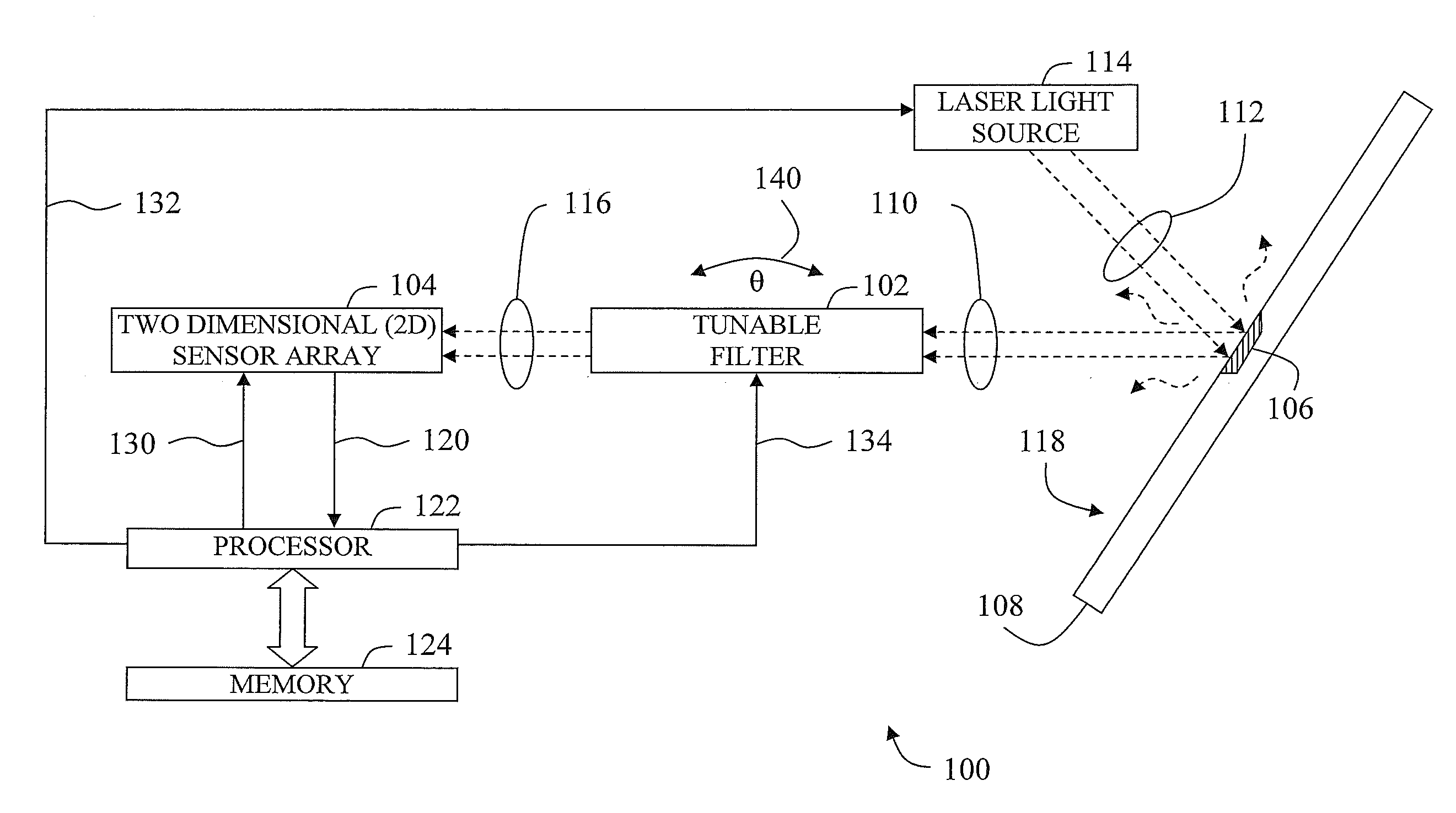
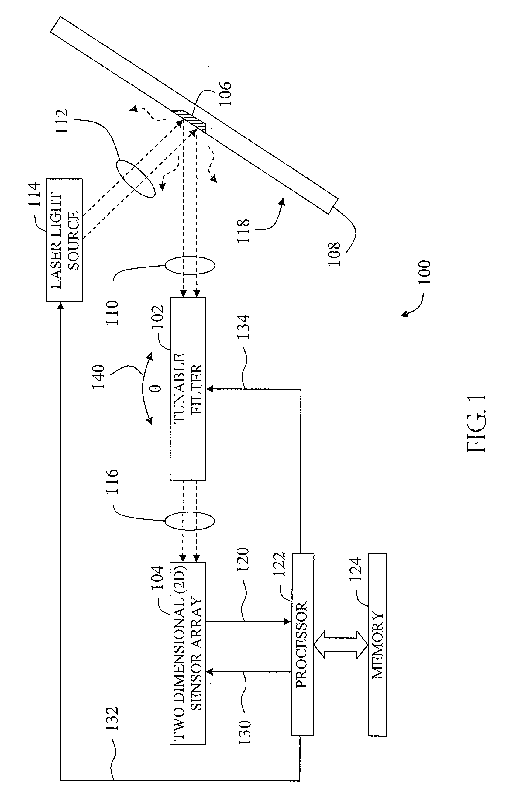
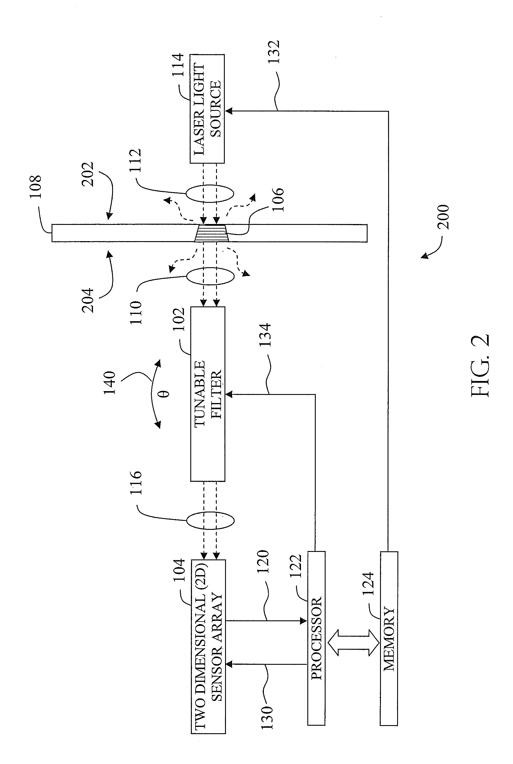
[0016]Systems and methods that are disclosed herein can provide spectral imaging so as to facilitate the comparatively rapid determination of material properties such as strain and / or stress. Two dimensional imaging facilitates the measurement of such properties upon an area of a subject material rather than upon a small spot or a narrow line, as is done according to contemporary methodology.

[0017]An example of an embodiment of a piezospectroscopic measurement apparatus can comprise a tunable optical filter that is configured to receive a first light beam and to provide a second light beam having a spectral profile corresponding to a tuning of the optical filter. The first light beam can be emitted by a portion of a subject material. A two-dimensional sensor array can have a plurality of pixels. Each pixel can be configured to receive at least a portion of the second light beam so as to produce a pixel signal. A plurality of pixel signals can be accumulated into an array signal for ...


PUM


Abstract

Systems and methods for spectral imaging are disclosed. Such spectral imaging can be used to determine properties of a subject material at different locations upon the surface and/or within the material. For example, strain and/or stress within an imaged area of the material can be determined. A system for spectral imaging can include a light source, a two-dimensional sensor array configured to image light from a two-dimensional area of a subject material, a filter configured to filter light from the subject material before the light is imaged and a processor in communication with the two-dimensional sensor array. The processor can be configured to determine a property of the subject material at a plurality of locations within the two-dimensional area of the subject material. Such spectral imaging systems can facilitate the performance of piezospectroscopic measurements of two-dimensional surfaces in a rapid manner while preserving accuracy.

Description

PRIORITY CLAIM[0001]This patent application claims the benefit of the priority date of U.S. provisional patent application Ser. No. 60 / 870,318, filed on Dec. 15, 2006 and entitled PIEZOSPECTROSCOPIC IMAGING USING A TUNABLE OPTICAL FILTER (docket no. M-16700-V1 US) pursuant to 35 USC 119. The entire contents of this provisional patent application are hereby expressly incorporated by reference.TECHNICAL FIELD[0002]The present invention relates generally to optics. The present invention relates more particularly to a piezospectroscopic imaging device for measuring material properties such as stress and strain that can provide high spectral resolution.BACKGROUND[0003]Piezospectroscopy (PS) includes the measurement of stress distributions within a material by measuring a shift in the peak wavelength of a particular luminescence band emitted by, for example, a collection of transition metal or rare-earth ions in the material. This is done while the material is optically excited with a las...

Claims


Application Information

Patent Timeline
IPC IPC(8): G01B11/16G01J3/44G02B27/32G01J3/28
CPCG01J3/12G01L1/24G01J3/2823
Inventor HEEG, BAUKEABBISS, JOHN B.KHIZHNYAK, ANATOLIY I.CLARKE, DAVID R.
Owner METROLASER
Why Eureka
Try Eureka