Lens driving device

a driving device and lens technology, applied in piezoelectric/electrostrictive/magnetostrictive devices, mountings, instruments, etc., can solve the problems of affecting the miniaturization of products, so as to achieve the effect of simplifying the structur

Inactive Publication Date: 2008-06-19
SAMSUNG ELECTRO MECHANICS CO LTD
View PDF4 Cites 57 Cited by
  • Summary
  • Abstract
  • Description
  • Claims
  • Application Information

AI Technical Summary

Benefits of technology

[0012]An aspect of the present invention provides a lens driving device which is more simplified in structure to achieve miniaturization thereof.
[0013]An aspect of the present invention also provides a lens driving device which attains a big driving distance with a lower input voltage, thereby ensuring superior driving resolution and minimal loss of a driving force.
[0014]An aspect of the present invention also provides a lens driving device which is simplified in a guide mechanism for guiding movement of a lens and moves the lens to move accurately and stably.

Problems solved by technology

This complicates an assembling structure and a process, and hinders miniaturization of the product.
However, in this conventional device, the driving rods are fixed so that a length of barrel cannot be changed.
Also, a driving signal of the device is an asymmetrical wave signal, not a sine wave signal, thereby complicating a driving circuit.

Method used


Image

  • Lens driving device
  • Lens driving device
  • Lens driving device

Examples


first embodiment

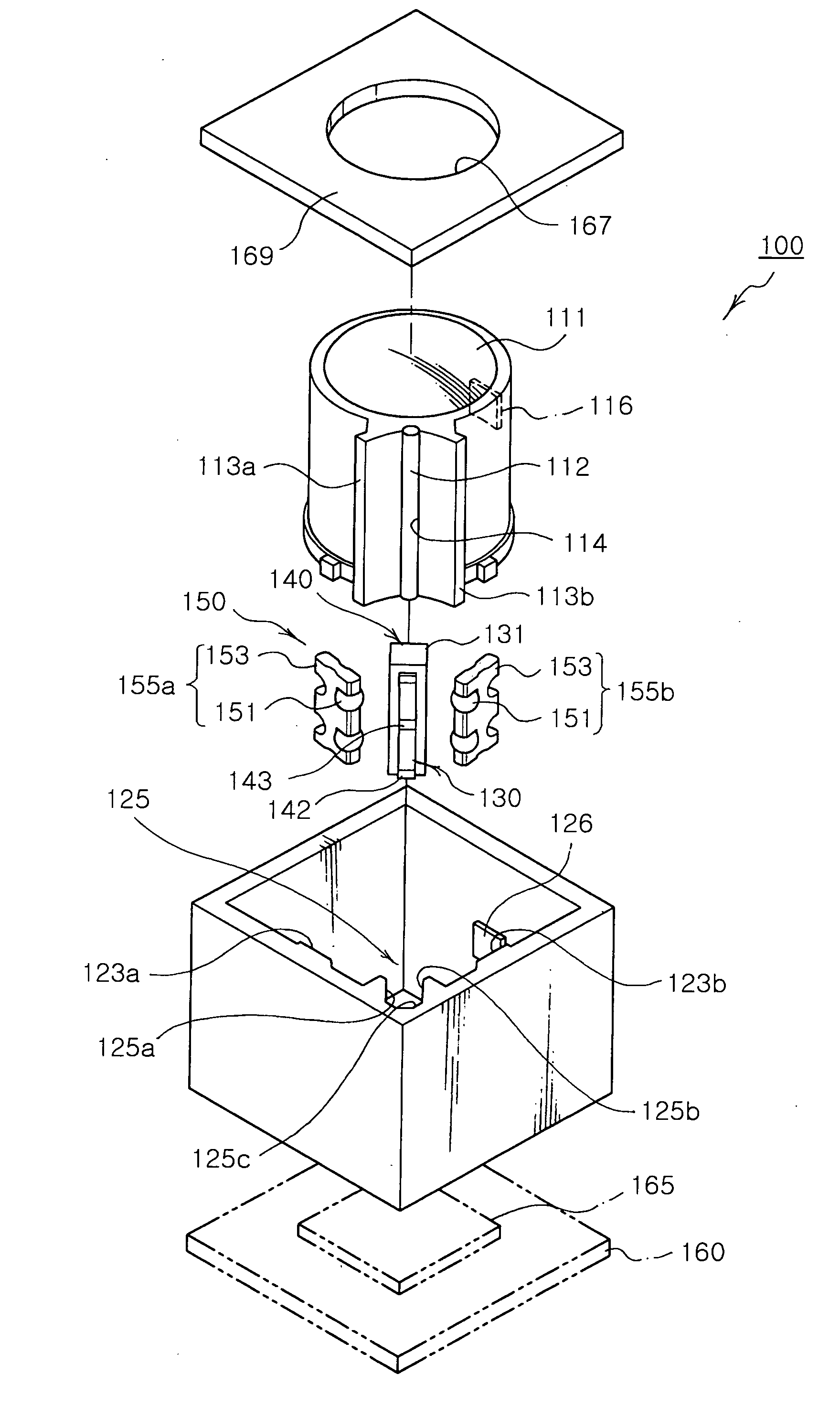
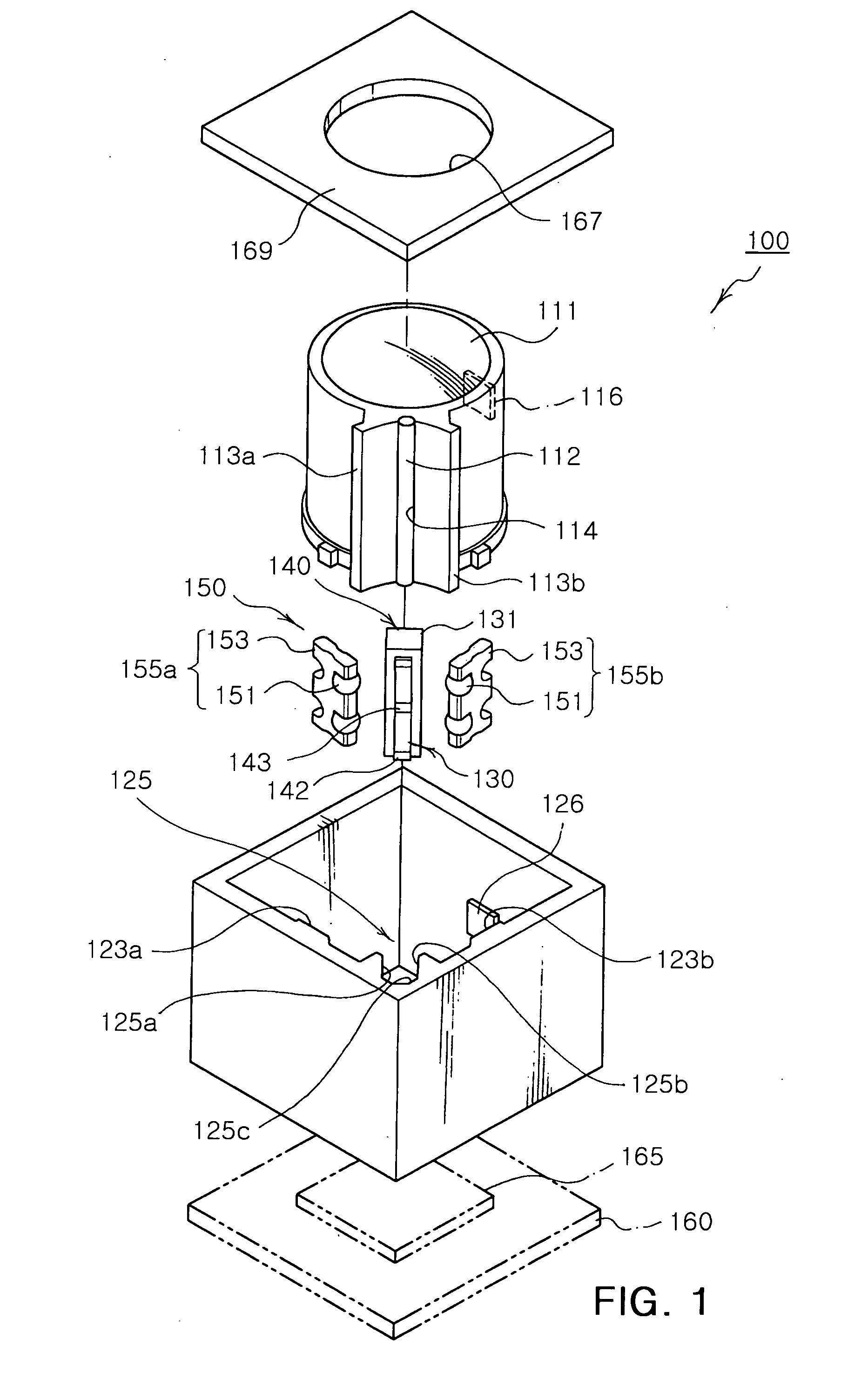
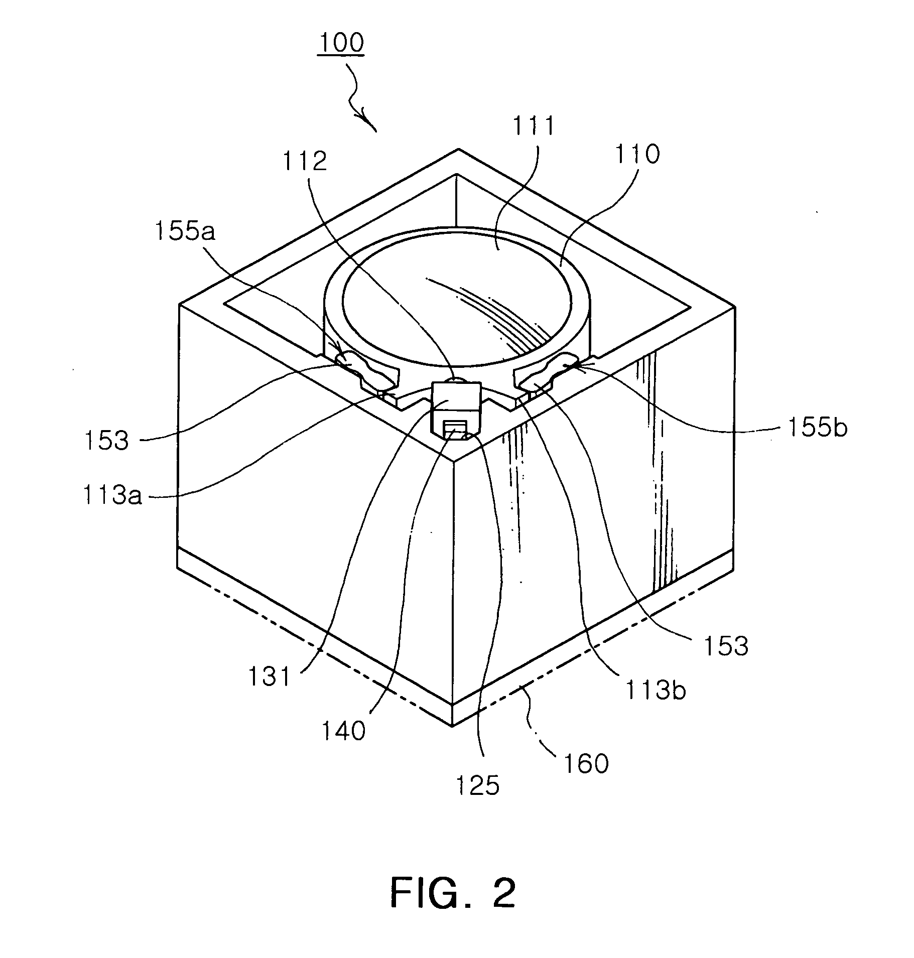
[0066]FIG. 1 is an exploded perspective view illustrating a lens driving device according to a first embodiment of the invention. FIG. 2 is an overall configuration view illustrating a lens driving device according to a first embodiment of the invention. FIG. 3 is a plan view illustrating a lens driving device according to a first embodiment of the invention.

[0067]The lens driving device 100 of the present embodiment includes a lens barrel 110, a housing 120, an actuator 130, a preload member 140 and a guiding part 150.

Lens Barrel

[0068]As shown in FIGS. 1 to 3, the lens barrel 110 has an inner space of a certain size for housing at least one lens 111 along an optical lens.

[0069]A friction member 112 of a predetermined length is formed on an outer surface of the lens barrel 110 and is adherently fixed to a groove 114 formed vertically in the outer surface of the lens barrel 110.

[0070]Here, the friction member 112 may be formed of alumina, ceramic or a metallic material such as super ...

second embodiment

[0099]FIG. 4 is an exploded perspective view illustrating a lens driving device according to a second embodiment of the invention. FIG. 5 is an overall configuration view illustrating a lens driving device according to a second embodiment of the invention and FIG. 6 is a plan view illustrating a lens driving device according to a second embodiment of the invention.

[0100]As shown in FIGS. 4 to 6, the lens driving device 200 includes a lens barrel 210, a housing 220, an actuator 230, a preload member 240 and a guiding part 250.

[0101]Here, components of the lens driving device 200 of the second embodiment that are identical to those of the previous embodiment, will be explained in no further detail and designated with numerals 20X.

Lens Barrel

[0102]As shown in FIGS. 4 to 6, the lens barrel 210 has at least one lens 211 arranged therein along an optical axis, and a groove 214 formed vertically on an outer surface thereof to have a friction member 212 of a certain length disposed thereon....

third embodiment

[0121]FIG. 7 is a perspective view illustrating a lens driving device according to a third embodiment of the present invention. FIG. 8 is an exterior view illustrating a lens driving device according to a third embodiment of the present invention. FIG. 9 is a perspective view illustrating a lens driving device, seen from the top, according to a third embodiment of the present invention. FIG. 10 is a perspective view illustrating a lens driving device according to a third embodiment of the invention. FIG. 11 is a plan view illustrating a lens driving device according to a third embodiment of the invention.

[0122]As shown in FIGS. 7 to 11, the lens driving device 300 includes a lens barrel 310, a housing 320, an actuator 330, a preload member 340 and a guiding part 350.

[0123]Here, components of the lens driving device 300 of the third embodiment that are identical to those of the previous embodiment, will be explained in no further detail and designated with numerals 30X.

Lens Barrel

[01...


PUM


Abstract

A lens driving device including: a lens barrel having at least one lens therein and provided with a friction member; a housing for housing the lens barrel therein; an actuator having a piezoelectric body disposed at an edge of the housing to apply a driving force, the piezoelectric body having at least one output member provided at one side thereof to be in contact with the friction member; a preload member disposed between the edge of the housing and the actuator to apply an elastic force toward the lens barrel; and a guiding part disposed between the housing and the lens barrel to guide the lens barrel to move in an optical axis direction. The lens driving device is simplified in a driving mechanism and thus reduced in size, while experiencing minimum loss of a driving power and ensuring more accurate and stable movement of the lens.

Description

CROSS-REFERENCE TO RELATED APPLICATIONS[0001]This application claims the priority of Korean Patent Application No. 2006-130488 filed on Dec. 19, 2006, in the Korean Intellectual Property Office, the disclosure of which is incorporated herein by reference.BACKGROUND OF THE INVENTION[0002]1. Field of the Invention[0003]The present invention relates to a lens driving device employed in an optical device, and more particularly, to a lens driving device which is simplified in a driving mechanism to achieve a smaller size, minimized in loss of a driving force for driving a lens and ensures more accurate and stable movement of the lens.[0004]2. Description of the Related Art[0005]In general, an optical apparatus includes a lens driving device for driving a lens using a cam structure, a screw or a piezoelectric element. The lens driving device employs a motor or the piezoelectric element to generate a driving force and the cam structure or the screw to transmit the driving force.[0006]There...

Claims


Application Information

Patent Timeline
Patent Type & Authority Applications(United States)
IPC IPC(8): G02B7/02
CPCG02B7/021G02B7/08H01L41/0906H01L41/083G02B13/001H10N30/202H10N30/50G02B7/04G02B7/09G02B7/10
Inventor KOC, BURHANETTINHWANG, JUNG WOOKKANG, BYUNG HOONKO, HYUN PHILL
Owner SAMSUNG ELECTRO MECHANICS CO LTD
Why Eureka
Try Eureka