Cluster bridged casting core

a technology of casting core and superalloy, which is applied in the direction of machines/engines, climate sustainability, waterborne vessels, etc., can solve the problems of slender legs being quite brittle, ceramic cores that must be specifically configured for the complex 3d turbine blades are yet more complex in configuration, and are subject to substantial centrifugal loads and corresponding stress

Active Publication Date: 2008-06-19
GENERAL ELECTRIC CO
View PDF17 Cites 30 Cited by
  • Summary
  • Abstract
  • Description
  • Claims
  • Application Information

AI Technical Summary

Problems solved by technology

Since the turbine blades rotate with the supporting rotor disk during operation, they are subject to substantial centrifugal loads and corresponding stress.
The ceramic core which must be then specifically configured for the complex 3D turbine blade is yet even more complex in configuration in view of its relatively large length to width and thickness correspondingly creating long and slender ceramic legs.
These slender legs are quite brittle in view of the high strength ceramic material used to withstand the high temperature of the molten metal during the casting process.
Accordingly, the ceramic core is quite fragile and is subject to inadvertent breakage during manufacture of the core itself, during handling of that core, and during the casting process.
Statistically, a small percentage of fabricated cores will break during the fabrication and use thereof and lead to a corresponding increase in cost of the manufacturing process.
A core broken during the casting process will typically lead to scrapping also of the so cast turbine blade.
Accordingly, ceramic core design includes features for strengthening thereof which are inherently limited by the final configuration of the turbine blade being cast.
Thicker or stouter ceramic cores correspondingly result in thinner and weaker turbine blades in view of the loss in resulting cast metal.
The external 3D configuration of a turbine blade is limited by the desired aerodynamic performance and efficiency of the engine, and simply making cores larger or blades larger decreases efficiency and performance of the turbine blade.
Furthermore, small ceramic ties may be preferentially located between the slender ceramic legs for bridging them together to increase the collective strength, but the ties necessarily result in a flow passage in the resulting turbine airfoil which may be undesirable for internal cooling performance.
The voids created by the core ligaments therefore interrupt the mechanical continuity and strength of the turbine blade typically in its shank region between the dovetail lobes and blade platform.
Yet further complicating the design of turbine blades is the ever increasing complexity of the internal cooling circuits, and the number of individual radial cooling channels therein, which correspondingly require even thinner and more slender ceramic legs in the ceramic core.
In one advanced turbine blade undergoing study, the numerous slender ceramic legs are additionally strengthened by using slender core ligaments, but those slender ligaments are themselves subject to breakage, which also renders the ceramic core unusable.

Method used


Image

  • Cluster bridged casting core
  • Cluster bridged casting core
  • Cluster bridged casting core

Examples


Embodiment Construction

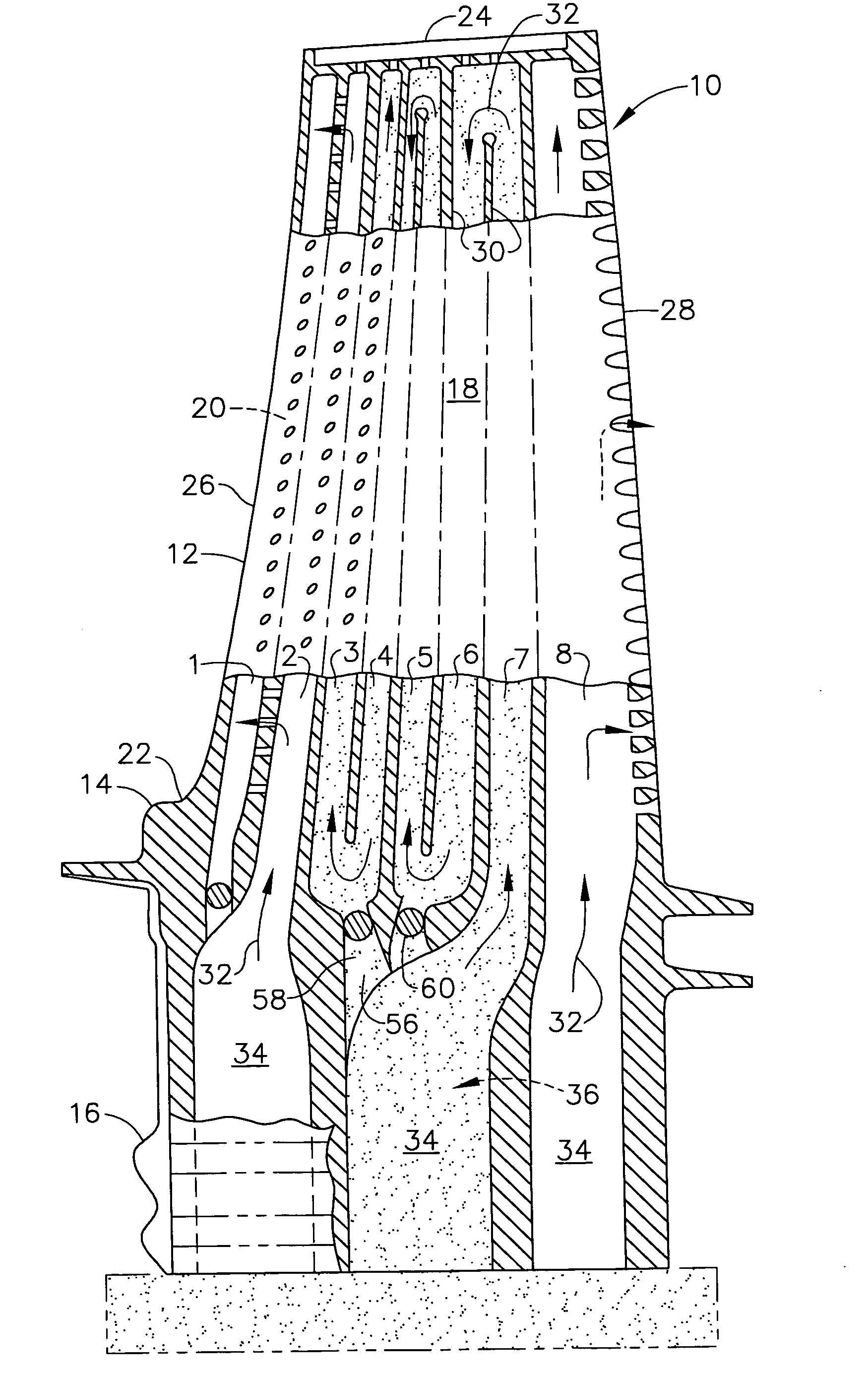
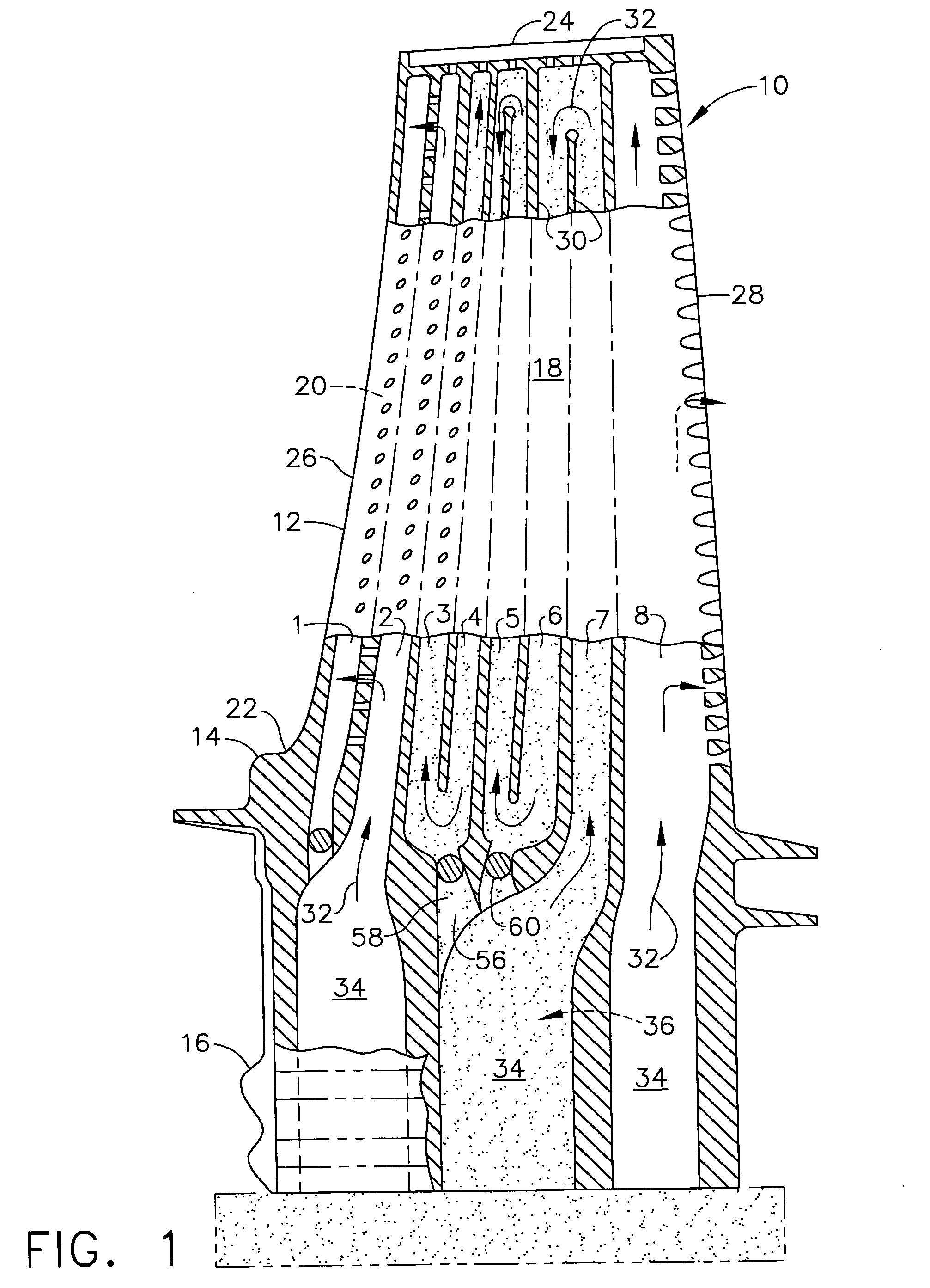
[0037]Illustrated in FIG. 1 is a first stage turbine rotor blade 10 configured for use in a gas turbine engine for extracting energy from hot combustion gases. The blade includes an airfoil 12 extending radially in span from an inner platform 14 which in turn is joined to a mounting dovetail 16 in a unitary assembly.

[0038]The platform 14 defines a portion of the radially inner boundary of the combustion gas flowpath in the engine and adjoins adjacent platforms in a full row of the turbine blades extending radially outwardly from the perimeter of a supporting rotor disk (not shown).

[0039]The dovetail 16 is an exemplary axial-entry dovetail with corresponding tangs or lobes configured for mounting in a complementary dovetail slot in the perimeter of the rotor disk which carries the centrifugal loads generated by the turbine blade during rotary operation of the disk during operation.

[0040]The airfoil 12 as illustrated in FIGS. 1 and 2 includes a generally concave pressure side 18 and a...


PUM

PropertyMeasurementUnit
areaaaaaaaaaaa
elevationaaaaaaaaaa
perimeteraaaaaaaaaa

Abstract

A casting core for a turbine blade includes a plurality of rods extending above a shank. The rods define internal cooling channels in the airfoil of the blade, and the shank defines an inlet channel in the dovetail of the blade. A plurality of stubs are clustered together at a bulb joined to the shank and radiate outwardly to integrally join different ones of the rods for increasing strength of the core.

Description

[0001]The U.S. Government may have certain rights in this invention pursuant to contract number N00019-04-C0093 awarded by the U.S. Department of the Defense.BACKGROUND OF THE INVENTION[0002]The present invention relates generally to gas turbine engines, and, more specifically, to casting of superalloy turbine blades therein.[0003]In a gas turbine engine, air is pressurized in a compressor and mixed with fuel in a combustor for generating hot combustion gases. Energy is extracted from the gases in turbine stages for powering the compressor and performing external work, such as powering a fan in a turbofan aircraft gas turbine engine application.[0004]Each turbine stage includes a stationary turbine nozzle having a row of nozzle vanes which discharge the combustion gases into a corresponding row of turbine rotor blades. Each blade includes an airfoil extending radially outwardly in span from an integral platform defining the radially inner flowpath boundary. The platform is integrall...

Claims


Application Information

Patent Timeline
Patent Type & Authority Applications(United States)
IPC IPC(8): F01D5/18B22D15/00
CPCB22C9/103F01D5/187Y02T50/671F05D2260/202Y02T50/676F05D2230/211Y02T50/673Y02T50/60B22C9/00B22C9/10
Inventor LEE, CHING-PANGBRASSFIELD, STEVEN ROBERT
Owner GENERAL ELECTRIC CO
Why Eureka
Try Eureka