Model-based turbocharger control

a turbocharger and control technology, applied in the direction of electric control, combustion engines, machines/engines, etc., can solve the problems of difficult if not impossible open-loop control of by-passes, inefficient operating zones in second and third zones,

Inactive Publication Date: 2008-06-26
INT ENGINE INTPROP CO LLC
View PDF11 Cites 32 Cited by
  • Summary
  • Abstract
  • Description
  • Claims
  • Application Information

AI Technical Summary

Benefits of technology

[0012]The present invention relates to a strategy in furtherance of the goal of making transitions between by-pass control and turbine vane control in the vicinity of the choke limit line seamless.
[0013]Briefly, the invention contemplates modeling a turbocharger by defining inside the efficient operation zone, a line that is spaced from and generally parallel with the choke limit line. For convenience the defined line will be referred to as an optimum efficiency line. When engine operation causes turbocharger operation to enter the portion of the efficient operation zone lying between the optimum efficiency line and the choke limit line, the high-pressure compressor vanes begin to be controlled in a particular way that is a function of the optimum efficiency line and the choke limit line. This control mode generally provides a smoother transition from vane control to by-pass control, and vice versa, and generally avoids choking of the high-pressure compressor.
[0016]Principles of the invention can be embodied in an engine control strategy without the inclusion of additional mechanical devices, making implementation of the inventive strategy cost-effective. In addition to improving engine performance, the invention can have a favorable effect on tailpipe emission compliance with applicable laws and regulations.
[0020]When the vanes have been substantially maximally opened and the high-pressure compressor stage has become unable by itself to provide sufficient boost, the high-pressure turbine by-pass is opened to begin routing exhaust flow to a low-pressure turbine that operates the low-pressure compressor stage, thereby avoiding choking of the charge air flow by the high-pressure compressor stage.

Problems solved by technology

The choke limit line demarcates the efficient operating zone from a second zone where efficiency suffers to such an extent that the second zone is deemed an inefficient operating zone.
Various interactions can take place during this transition due to various factors and they may be unpredictable.
The task of satisfactorily reconciling them by modifying the respective control strategies for the vanes and the by-pass when control of the turbocharger transitions from closed-loop of the vanes to open-loop control of the by-pass is difficult if not impossible as a practical matter.

Method used


Image

  • Model-based turbocharger control
  • Model-based turbocharger control
  • Model-based turbocharger control

Examples


Embodiment Construction

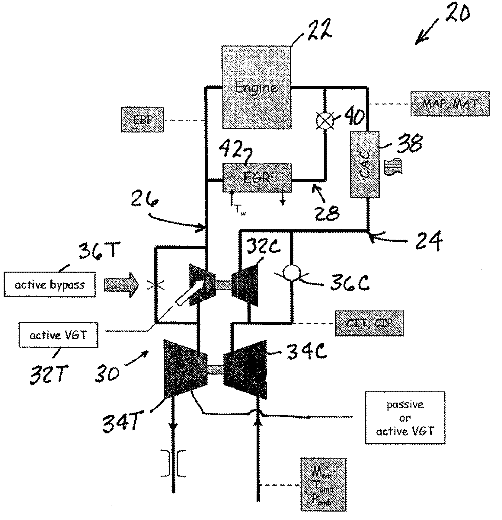
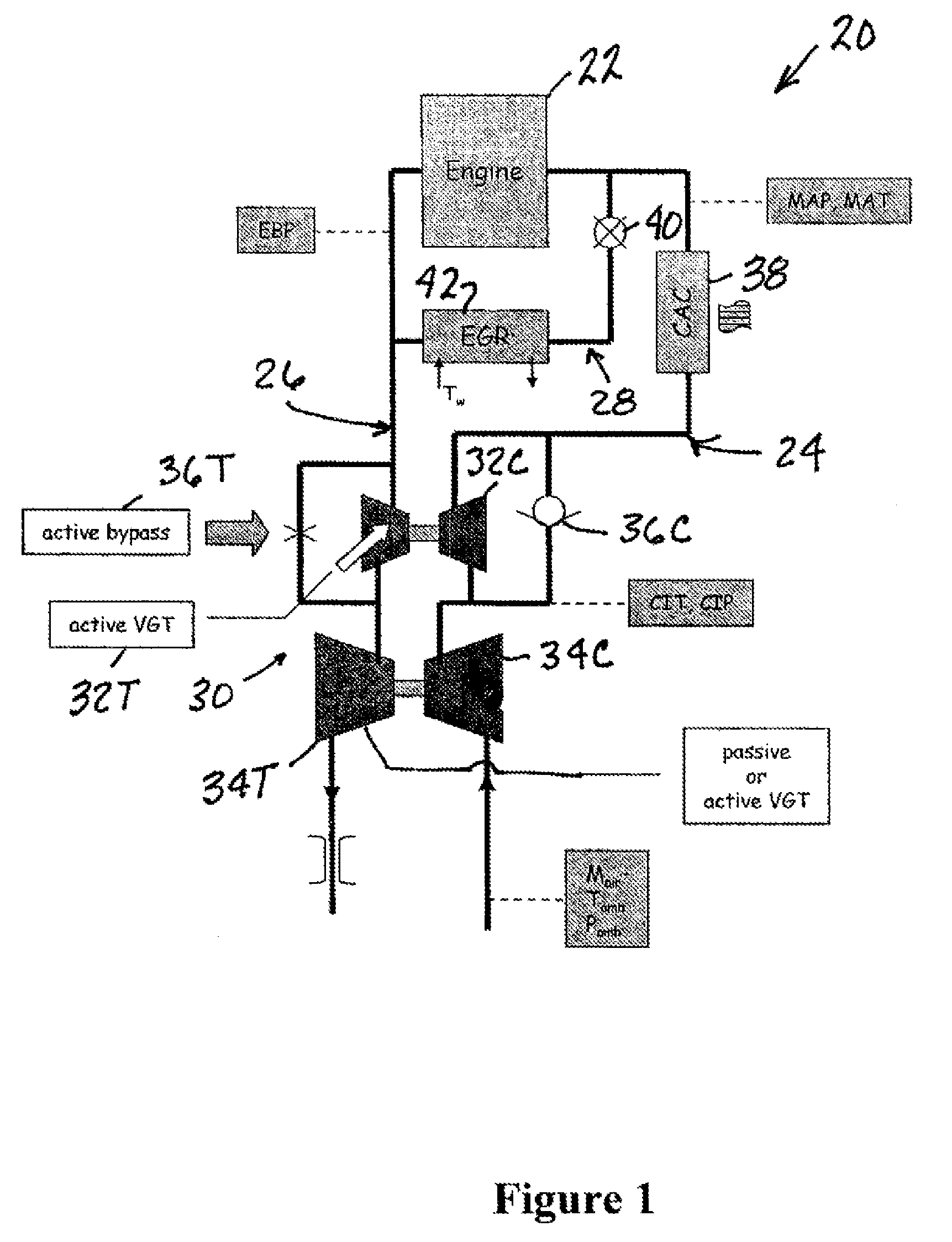
[0030]FIG. 1 shows an exemplary internal combustion engine system 20 comprising an engine 22 containing cylinders in which combustion occurs, an intake system 24 through which charge air can enter engine 22 and an exhaust system 26 through which exhaust gasses resulting from combustion of air-fuel mixtures in the cylinders exit. An EGR system 28 provides for exhaust gas to be recirculated from exhaust system 26 to intake system 24.

[0031]Engine system 20 is representative of a turbocharged diesel engine comprising a two-stage turbocharger 30 that has a high-pressure turbine stage 32T in exhaust system 16 for operating a high-pressure compressor stage 32C in intake system 14 and a low-pressure turbine stage 34T in exhaust system 16 for operating a low-pressure compressor stage 34C in intake system 14.

[0032]A controlled by-pass valve 36T parallels turbine 32T, and a check-type by-pass valve 36C parallels compressor 32C. A charge air cooler 38 is downstream of compressor 32C and valve 3...


PUM


Abstract

When a high-pressure compressor stage operates in an efficient operating zone defined on a compressor performance to one side of an optimum performance line that is spaced from but generally parallel to a choke limit line, the turbocharger is controlled by closed-loop control of vanes of the high-pressure turbine stage while a by-pass around the high-pressure turbine stage is kept closed. When the high-pressure compressor stage operates in a zone between the optimum performance line and the choke limit line, the vanes of the high-pressure turbine stage are increasingly opened as operation of the high-pressure compressor stage increasingly approaches the choke limit line. When the vanes have been maximally opened and the high-pressure compressor stage has become unable to provide sufficient boost, the high-pressure turbine by-pass is opened to begin routing exhaust flow to a low-pressure turbine that operates a low-pressure compressor stage, thereby avoiding choking of the charge air flow by the high-pressure compressor stage.

Description

FIELD OF THE INVENTION [0001]This invention relates to turbocharged internal combustion engines, particularly to a turbocharger control strategy for a motor vehicle diesel engine.BACKGROUND OF THE INVENTION [0002]Turbocharged diesel engines are powerplants of many large motor vehicles that are presently being manufactured in North America. A two-stage turbocharger, one type that can be used in such an engine, comprises high- and low-pressure turbines in series flow relationship in the exhaust system that operate high- and low-pressure compressors in series flow relationship in the intake system to develop boost. A single-stage turbocharger has only a single turbine and a single compressor.[0003]The high-pressure turbine of a particular type of two-stage turbocharger has vanes whose position can be set by an associated actuator using a control strategy to control boost and / or back-pressure. A turbocharger that has such vanes is sometimes called a variable geometry turbocharger, or si...

Claims


Application Information

Patent Timeline
Patent Type & Authority Applications(United States)
IPC IPC(8): F02D23/00F02B33/42
CPCF02B37/013F02B37/12F02B37/16F02B37/004F02B37/24F02D41/0007Y02T10/144F02B37/18Y02T10/12F02B39/16F02D23/00
Inventor DE OJEDA, WILLIAM
Owner INT ENGINE INTPROP CO LLC
Why Eureka
Try Eureka