Firearm suppressor, mounting system and mounting method

a technology for suppressors and firearms, applied in the field of improved, can solve the problems of reducing group unity, reducing the effect of muzzle sound, and reducing the chaos of close-quarters comba

Inactive Publication Date: 2008-06-26
MCCLELLAN W THOMAS
View PDF14 Cites 56 Cited by
  • Summary
  • Abstract
  • Description
  • Claims
  • Application Information

AI Technical Summary

Benefits of technology

[0006]It is accordingly an object of the invention to provide an improved firearm suppressor, a mounting system and a mounting method, which overcome the hereinafore-mentioned disadvantages of the heretofore-known devices and methods of this general type and which reduce the effects of muzzle sound, muzzle blast, visible muzzle flash and invisible infrared flash of firearms.

Problems solved by technology

The confusion and chaos of close-quarters combat is worsened by multidirectional unexpected muzzle blasts.
The futile use of earplugs only restricts communication, reduces group unity and lessens awareness of the surroundings.
No suppressor can be effective unless it can first “contain the explosion” of the propellant gases.
The minor turbulences created by those prior art baffles do little to effectively suppress any significant energy.

Method used


Image

  • Firearm suppressor, mounting system and mounting method
  • Firearm suppressor, mounting system and mounting method
  • Firearm suppressor, mounting system and mounting method

Examples


Embodiment Construction

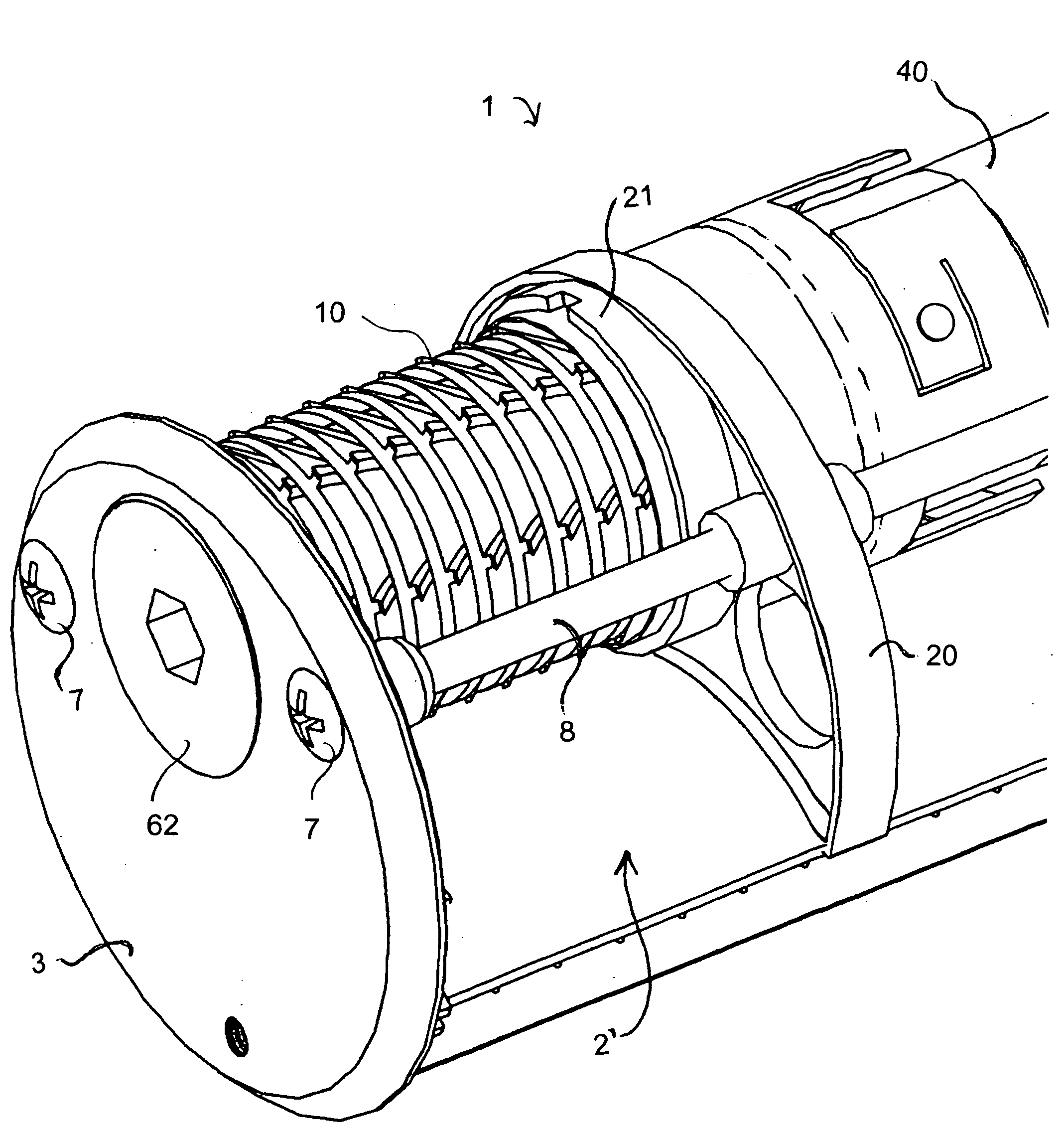
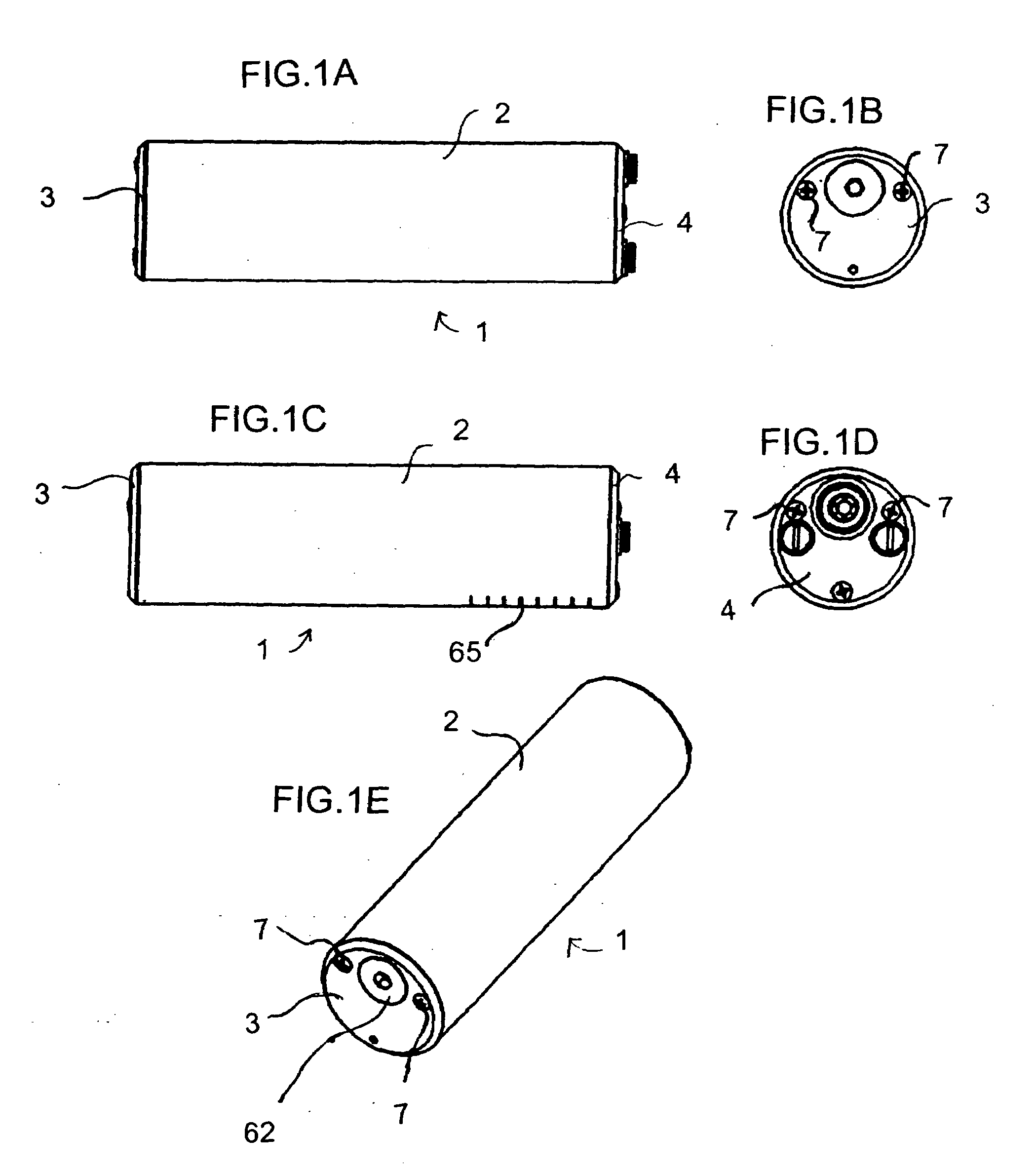
[0111]Referring now to the figures of the drawings in detail and first, particularly, to FIGS. 1A-1E thereof, there is seen a firearm suppressor 1 in an assembled but dismounted condition, having a cover or housing 2 with a front end cap 3, a rear end cap 4 and vents 65. FIGS. 2A-2C and FIGS. 3-6 show the suppressor 1 mounted on a firearm 5 having a sight 6.

[0112]FIGS. 7-10 illustrate a stripper member or cone according to the invention, whereas FIGS. 11 and 12 show eight stripper members or cones 10 assembled with a stabilizer bar 11 within an interior or lumen 2′ of the housing or cover 2. The stripper cones 10 engage and deflect quickly expanding gases in their forward and angular trajectory. The stripper cones 10 have sharpened upstream edges 12 for catching and deflecting a gas stream into the stripper cones and rounded downstream edges 13 providing aerodynamic surfaces or airfoils for pulling additional gas into the stripper cones 10 acting as a gas trap. The stripper cones 10...


PUM


Abstract

A firearm suppressor includes a housing to be mounted to a firearm. The housing defines a lumen therein for receiving gases from the firearm. At least one stripper member is disposed in the lumen for engaging and deflecting the gases. At least one one-way flow element is disposed downstream of the at least one stripper member in gas flow direction for permitting a one-way flow of the gases. At least one decompression chamber is disposed downstream of the at least one one-way flow element for reducing energy in the gases. At least one vent valve is disposed downstream of the at least one decompression chamber for expelling the gases into the atmosphere. A mounting system and a mounting method are also provided.

Description

BACKGROUND OF THE INVENTION[0001]1. Field of the Invention[0002]The invention relates to an improved firearm suppressor. The invention also relates to a mounting system and a mounting method.[0003]2. Description of the Related Art[0004]Firearm suppressors are intended to reduce the nerve racking, shooter revealing, and ear damaging effects of muzzle sound, muzzle blast, visible muzzle flash and invisible infrared flash of firearms. The confusion and chaos of close-quarters combat is worsened by multidirectional unexpected muzzle blasts. The futile use of earplugs only restricts communication, reduces group unity and lessens awareness of the surroundings. The problem must be attacked at its source, which is the muzzle.[0005]No suppressor can be effective unless it can first “contain the explosion” of the propellant gases. The prior art baffles form small, partially or non-vented, symmetrical, concave walled compartments which create perfect “reflection contours.” The reflected waves ...

Claims


Application Information

Patent Timeline
Patent Type & Authority Applications(United States)
IPC IPC(8): F41A21/30
CPCF41A21/34F41A21/30
Inventor MCCLELLAN, W.THOMAS
Owner MCCLELLAN W THOMAS
Why Eureka
Try Eureka