Heat transfer duct fastening structure
- Summary
- Abstract
- Description
- Claims
- Application Information
AI Technical Summary
Benefits of technology
Problems solved by technology
Method used
Image
Examples
second embodiment
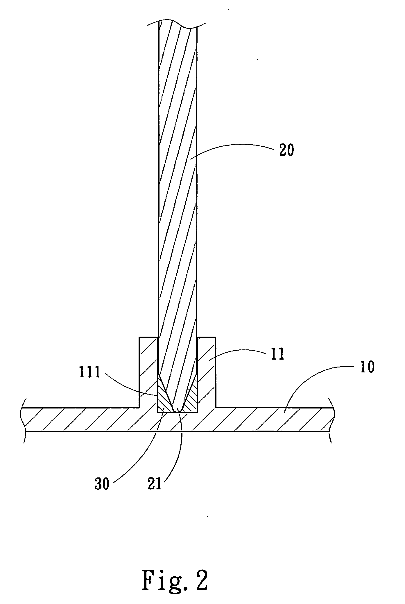
[0011]Refer to FIG. 3 for the invention. The base 10 has a sufficient thickness to allow the coupling portion 11 to be formed thereon at a desired depth to become a trough. The heat transfer duct 20 is inserted into the coupling portion 11 to form a tight coupling. The heat transfer duct 20 and the base 10 are soldered through the soldering paste 30 to become integrated. Therefore fast heat dissipation can be achieved.
third embodiment
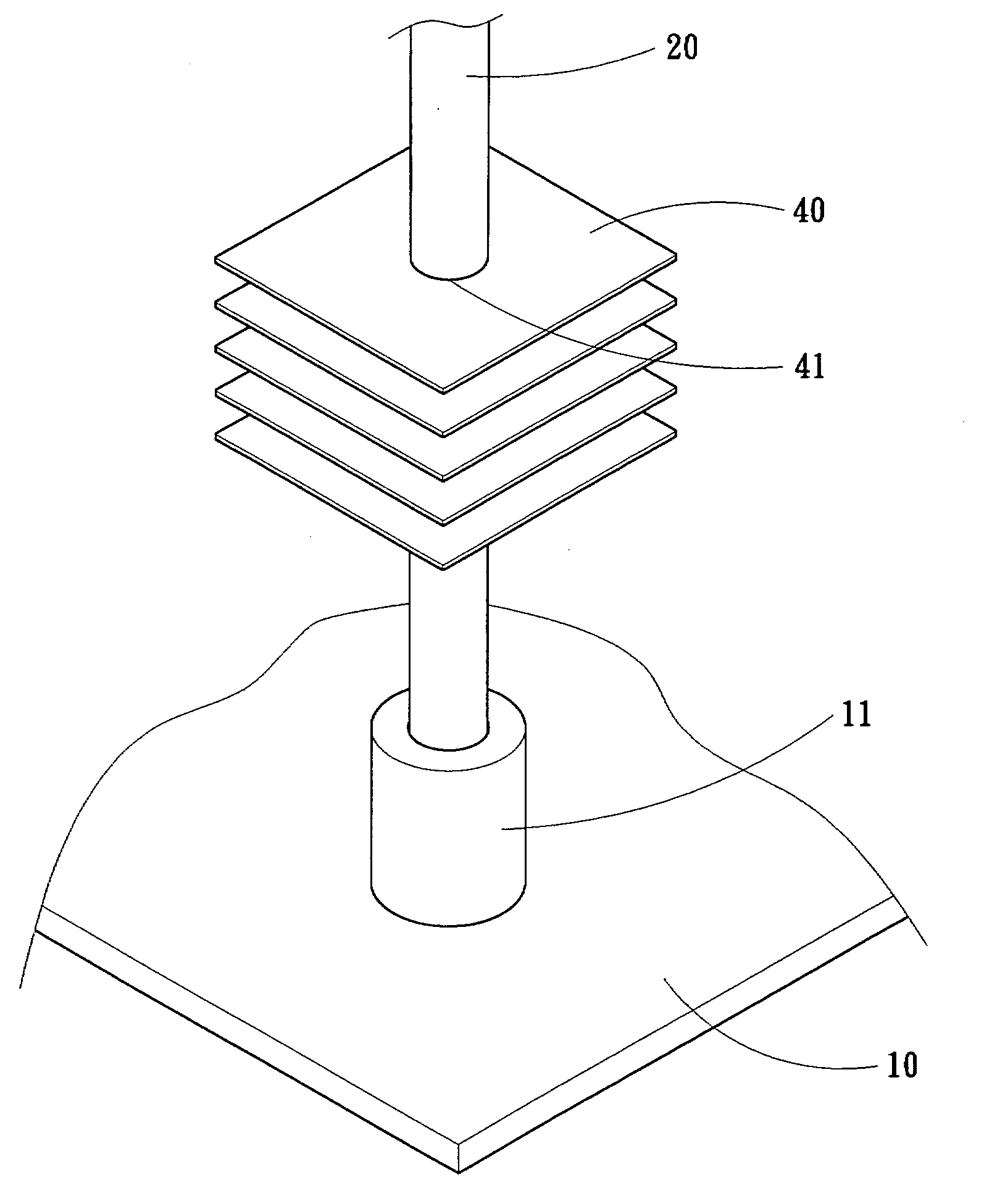
[0012]Refer to FIG. 4 for the invention. This invention can also be used with one or more heat dissipating fins 40. The heat dissipating fin 40 is made of metal and has an opening 41 running though by the heat transfer duct 20. Then they are soldered together through the soldering paste 30. Such a structure can greatly increase the contact area with the air to enhance the heat dissipating efficiency.
PUM
 Abstract
Description
Claims
Application Information
 - R&D
- Intellectual Property
- Life Sciences
- Materials
- Tech Scout
- Unparalleled Data Quality
- Higher Quality Content
- 60% Fewer Hallucinations
Browse by: Latest US Patents, China's latest patents, Technical Efficacy Thesaurus, Application Domain, Technology Topic, Popular Technical Reports.
© 2025 PatSnap. All rights reserved.Legal|Privacy policy|Modern Slavery Act Transparency Statement|Sitemap|About US| Contact US: help@patsnap.com


