Method for manufacturing an electrokinetic infusion pump

a technology of electrokinetic infusion pump and manufacturing method, which is applied in the direction of positive displacement liquid engine, machine/engine, paper/cardboard container, etc., can solve the problem that the inactivated membrane portion cannot allow fluid flow, and achieve the effect of encouraging adhesion

Inactive Publication Date: 2008-06-26
LIFESCAN INC
View PDF6 Cites 99 Cited by
  • Summary
  • Abstract
  • Description
  • Claims
  • Application Information

AI Technical Summary

Benefits of technology

[0007]Once selected portions of the membrane are inactivated, the resulting treated membrane can be laminated to create a fluid flow path. The treated membrane can be laminated between first and second sheets of lamination film that include one or more perforations therethrough. Each perforation can be aligned with an active region of the treated membrane such that the resulting laminated membrane has a perforation at a top portion and a bottom portion of each active region to define a fluid

Problems solved by technology

Inactivated membrane portion

Method used


Image

  • Method for manufacturing an electrokinetic infusion pump
  • Method for manufacturing an electrokinetic infusion pump
  • Method for manufacturing an electrokinetic infusion pump

Examples


Embodiment Construction

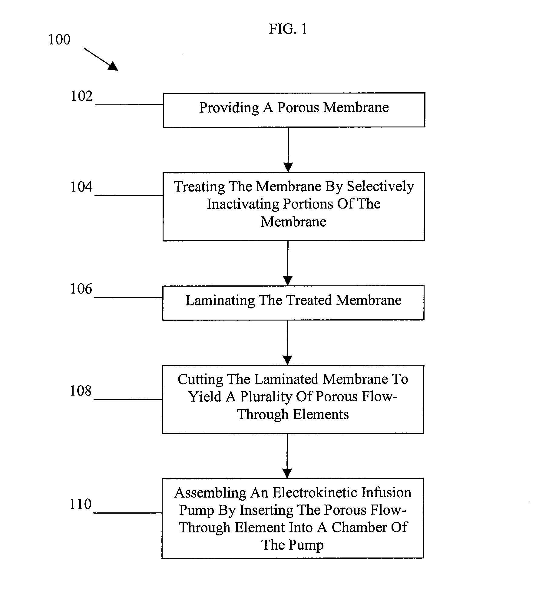
[0019]Certain exemplary embodiments will now be described to provide an overall understanding of the principles of the structure, function, manufacture, and use of the devices and methods disclosed herein. One or more examples of these embodiments are illustrated in the accompanying drawings. Those skilled in the art will understand that the devices and methods specifically described herein and illustrated in the accompanying drawings are non-limiting exemplary embodiments and that the scope of the present invention is defined solely by the claims. The features illustrated or described in connection with one exemplary embodiment may be combined with the features of other embodiments. Such modifications and variations are intended to be included within the scope of the present invention.

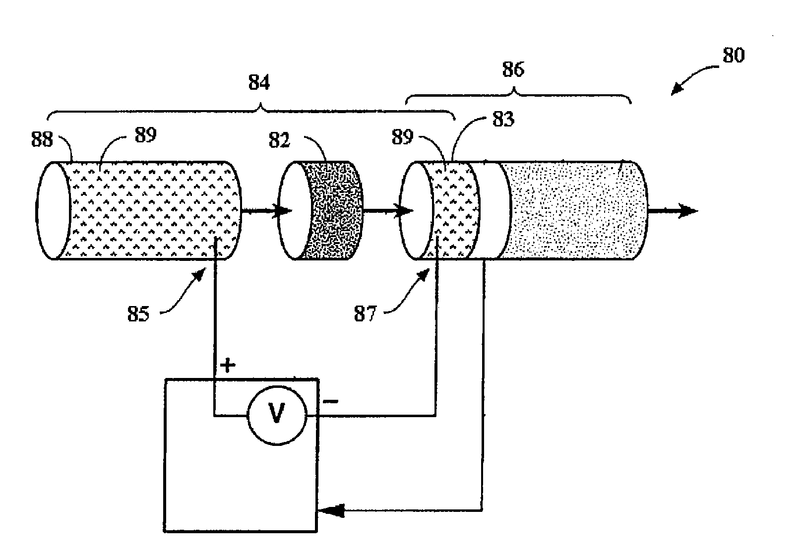
[0020]The features disclosed herein are applicable to a variety of electrokinetic infusion pump systems. For example, the methods disclosed herein can be used in the manufacture of electrokinetic infu...


PUM

PropertyMeasurementUnit
Thicknessaaaaaaaaaa
Thicknessaaaaaaaaaa
Lengthaaaaaaaaaa

Abstract

A method for producing a porous flow-through element for use in an electrokinetic infusion pump is provided and generally includes providing a porous membrane that is entirely porous along both its length and width, treating the membrane by selectively inactivating portions of the membrane in a desired pattern to define active regions that allow fluid flow therethrough and inactive regions that do not, and laminating the treated membrane. Various techniques can be used to treat the membrane including, for example, applying a heated embossing die to the membrane, contacting selected portions of the membrane with laser energy, applying a pore-penetrating chemical to the membrane, and cutting and removing selected portions of the membrane. The resulting treated membrane can be laminated between opposed films having one or more perforations therethrough with each perforation being aligned with an active region to define a fluid flow pathway therebetween.

Description

FIELD OF THE INVENTION[0001]The present invention relates to methods of manufacturing an electrokinetic infusion pump and more particularly to methods for producing a porous flow-through element for use in an electrokinetic infusion pump.BACKGROUND OF THE INVENTION[0002]Electrokinetic pumps provide for liquid displacement by applying an electric potential across a porous dielectric media that is filled with an ion-containing electrokinetic solution. Properties of the porous dielectric media and ion-containing solution (e.g., permittivity of the ion-containing solution and zeta potential of the solid-liquid interface between the porous dielectric media and the ion-containing solution) are predetermined such that an electrical double-layer is formed at the solid-liquid interface. Thereafter, ions of the electrokinetic solution within the electrical double-layer migrate in response to the electric potential, transporting the bulk electrokinetic solution with them via viscous interactio...

Claims


Application Information

Patent Timeline
IPC IPC(8): B32B38/10B32B38/06B23P15/00
CPCF04B43/0054Y10T29/49236Y10T156/10Y10T156/1039Y10T156/1052
Inventor BOHM, SEBASTIANWIARD, RICHARD
Owner LIFESCAN INC
Why Eureka
Try Eureka