Reactive power control for operating a wind farm

a technology of reactive power control and wind farm, which is applied in the direction of electric generator control, instruments, machines/engines, etc., can solve the problems of high electrical stress and wear, often overlooked reactive power management, etc., and achieves the effect of enhancing the reserve of available reactive power, contributing to the stability of the electrical grid, and reducing the risk of failur

Inactive Publication Date: 2008-06-26
INGETEAM POWER TECH
View PDF41 Cites 117 Cited by
  • Summary
  • Abstract
  • Description
  • Claims
  • Application Information

AI Technical Summary

Benefits of technology

[0017]According to this aspect of a non-limiting exemplary embodiment, the WFCC is aware of the wind farm's reserve of reactive power. This is a great advantage for the wind farm operator or utility because this reserve can be used to contribute to the stability of the electrical grid. Eventually, the availability of such a reactive power reserve can be economically recognized by means of a bonus.
[0018]Furthermore, in exemplary embodiments of the present invention a higher reserve of reactive power can be accomplished. The WFCC is able to follow demand, in one embodiment given by the utility, by enhancing the reserve of available reactive power. This functionality is achieved, if necessary, by prioritizing the reactive power reserve over the real power generation.
[0019]Another aspect of an embodiment of the present invention is that the reactive power compensation is mainly managed by the wind turbines that have higher instantaneous reactive power capacity due to the fact that the wind turbines generate or consume reactive power proportionally to their capacit...

Problems solved by technology

However, reactive power management is often not considered as a key player for keeping the electrical network stable.
That is, reactive power compensation is carried out by all th...

Method used


Image

  • Reactive power control for operating a wind farm
  • Reactive power control for operating a wind farm
  • Reactive power control for operating a wind farm

Examples


Embodiment Construction

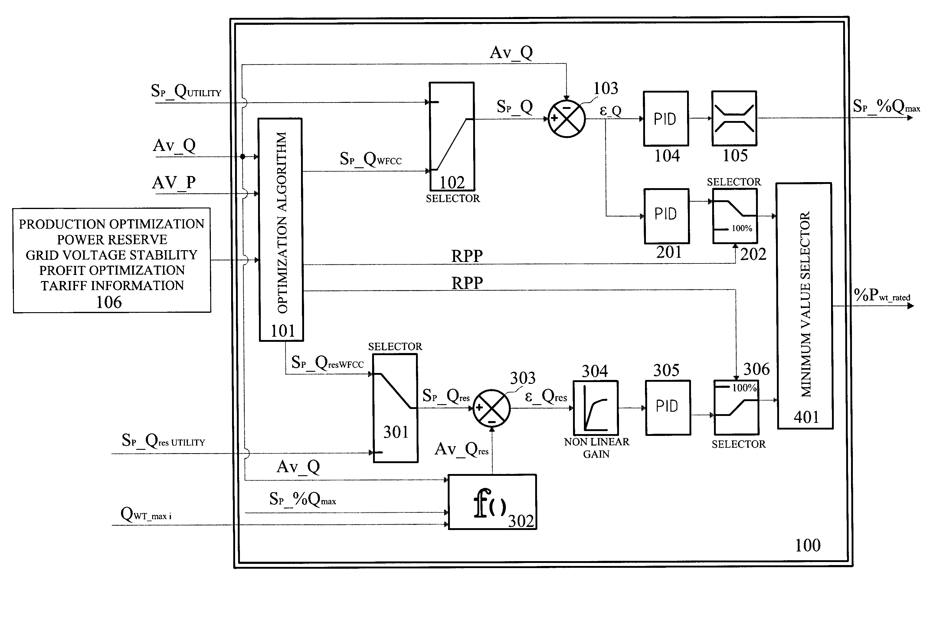
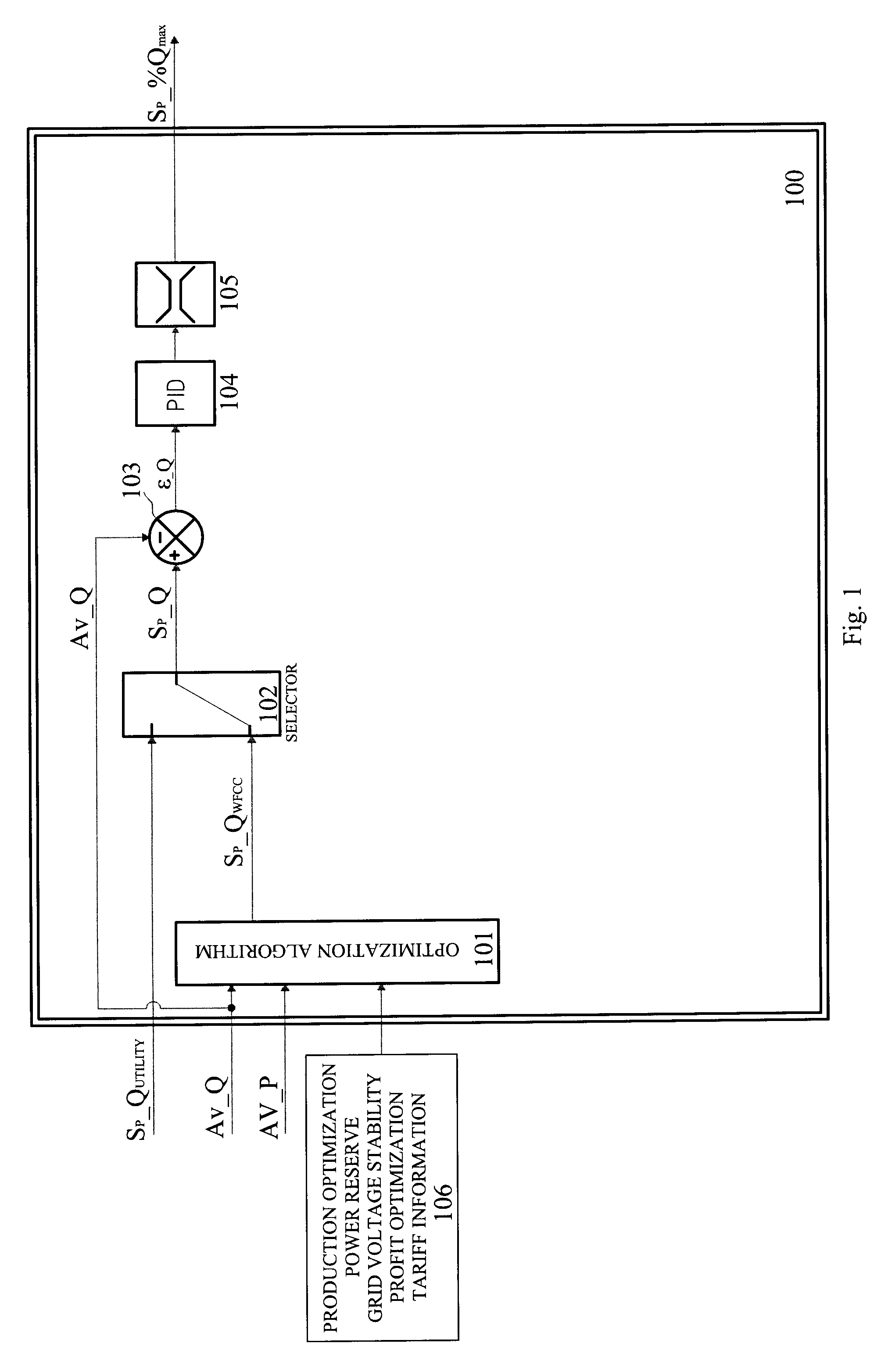
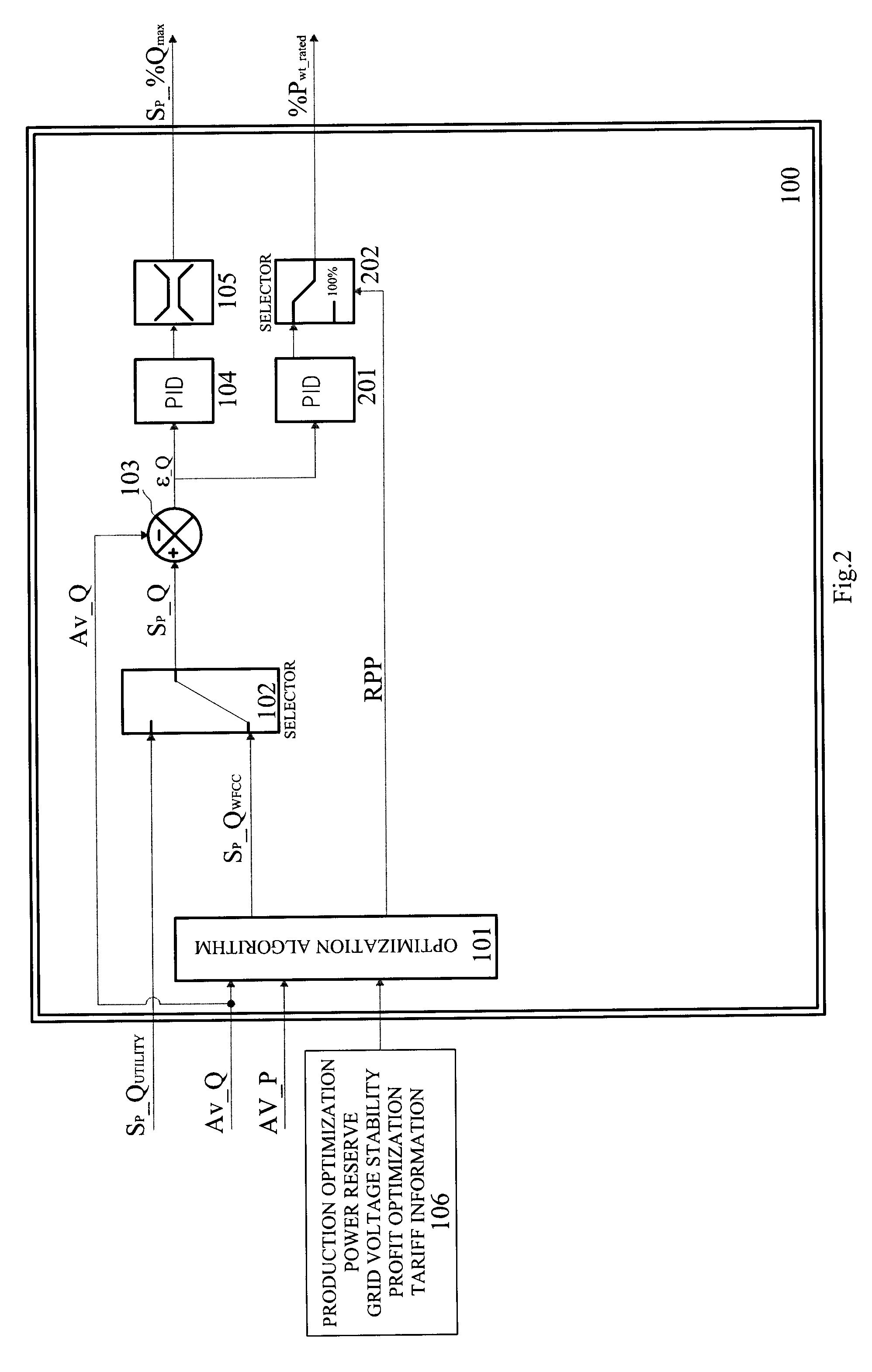
[0030]A reactive power control system that provides an optimum control of the reactive power compensation in a wind farm is described below. Several drawings will be referenced only as illustration for the better understanding of the description. Furthermore, the same reference numbers will be used in the drawings and in the description to refer to the same or like elements.

[0031]An exemplary topology of the wind farm with the reactive power control system is shown in FIG. 6. This system is comprised of a plurality of wind turbines (600a through 600e) and two subsystems: the wind farm central control (WFCC) (100), shown in FIGS. 1-4, which might be located in the substation or point of common coupling (PCC) (601), and the wind turbine relative control (WTRC) (500), shown in FIG. 5, which is carried out in at least one of the wind-turbines in the wind farm (see 500a through 500e in FIG. 6). The objective of this system is to follow a given setpoint of reactive power for the wind-farm...


PUM


Abstract

A system and method of reactive power regulation in a wind farm having a plurality of wind turbines that provides optimum control of the reactive power compensation in the wind farm and is able to keep a reactive power reserve in order to support eventual grid contingencies.

Description

FIELD OF THE INVENTION[0001]Methods and apparatuses consistent with the present invention are related to the field of wind power generation, more particularly to the reactive power control for operating a wind farm having multiple wind turbines.BACKGROUND OF THE INVENTION[0002]In the last few years, wind power production has become a very important energy source. Cumulative wind power worldwide is increasing remarkably and so is its share in the mix of energy production. Consequently, generation of energy from wind farms should contribute to the stability of the electrical network which is directly related to the generation or consumption of reactive power. Thus, it is necessary to perform a reactive power control in the wind farms.[0003]However, reactive power management is often not considered as a key player for keeping the electrical network stable. Generally, reactive power production plays a secondary role in wind farm power production strategy and is usually based on the loca...

Claims


Application Information

Patent Timeline
IPC IPC(8): F03D9/00G06Q30/00
CPCH02J3/1885H02J3/386Y02E40/32Y02E10/763H02J3/46H02J2300/28H02J3/381Y02E10/76Y02E40/30H02J3/50
Inventor RIVAS, GREGORIOGARMENDIA, IKERELORRIAGA, JOSUMAYOR, JESUSPEREZ BARBACHANO, JAVIERSOLE, DAVIDACEDO, JORGE
Owner INGETEAM POWER TECH
Why Eureka
Try Eureka