LED lighting device for refrigerated food merchandising display cases

a technology for refrigerated food and display cases, which is applied in the direction of domestic lighting, lighting applications, applications, etc., can solve the problems of short life of fluorescent lighting tubes, food store owners, and many characteristics of fluorescent lights

Inactive Publication Date: 2008-06-26
DE CASTRIS PIERRE
View PDF15 Cites 109 Cited by
  • Summary
  • Abstract
  • Description
  • Claims
  • Application Information

AI Technical Summary

Benefits of technology

[0001]This present invention relates to an LED lighting device for use as a replacement of fluorescent lights in a light tube fixtures mounted in refrigerated food display cases and more specifically to an LED lighting device having reduced energy consumption and reduce heat generation.

Problems solved by technology

However, fluorescent lights possess many characteristics which constitute major disadvantages for the food store owners.
The disadvantages include the short lifetime of the fluorescent lighting tube, low efficiency at low temperatures approaching freezing temperatures and below freezing temperatures, high power requirements, counter productive heat injection within the refrigerated volume, low durability and high electromagnetic interference which can be detrimental to other electrical systems.
In addition, specialty versions of fluorescent lighting systems incorporating higher intensity light and plastic shield protection against cold temperatures are not economical and do not prevent heat generation inside the refrigerated volume.
Yasumoto et al. does not disclose any specific means for securing their lighting device in any form of fixture, fluorescent or otherwise, and do not disclose any form of electrical apparatus for adapting the relatively low voltage requirements of an LED circuit to the necessarily higher voltage of a fluorescent fixture or even conventional line current.
The Gartner lighting device is thus incompatible with a fluorescent fixture, with its requirement for two parallel male electrical connector pins extending from each end of the lighting element, as provided by the present LED replacement device for fluorescent lighting.
Madadi et al. do not provide any form of reflector or diffuser means with their light, as they intend it to be installed within a double faced, back lighted sign (e.g., exit signs, etc.).
Moreover, as they intend their light to be used only in such relatively compact installations, they do not provide the conventional double parallel pin connectors at each end of the bulb, as is provided in the present LED replacement lighting.
Moreover, each end of the Hunter lamp includes a flexible cable extending therefrom, which is not compatible for installation in a conventional fluorescent light fixture.
However, even with recently developed “super bright” LEDs, the light output of a single LED is relatively weak in comparison to a conventional fluorescent light unit at room temperature.

Method used


Image

  • LED lighting device for refrigerated food merchandising display cases
  • LED lighting device for refrigerated food merchandising display cases
  • LED lighting device for refrigerated food merchandising display cases

Examples


first embodiment

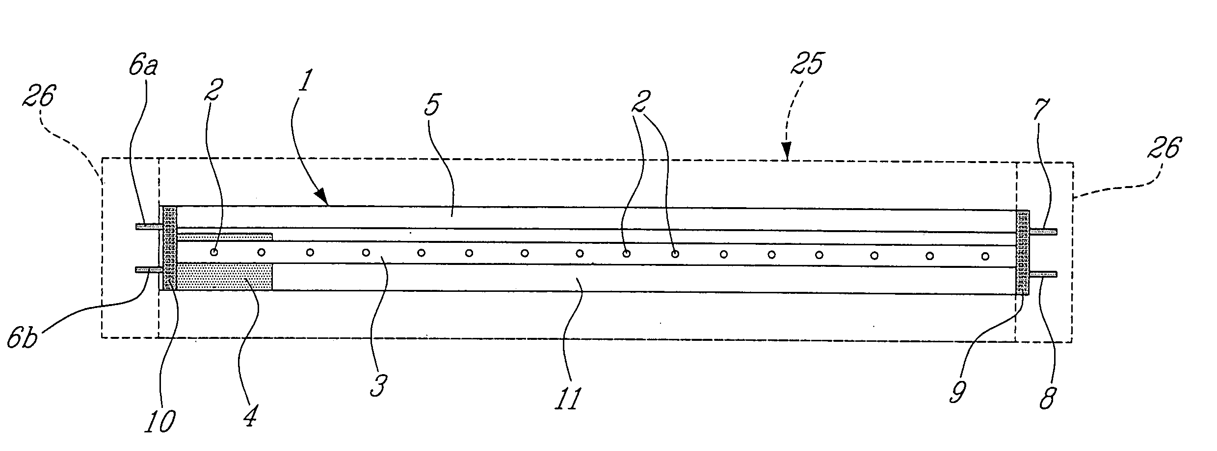
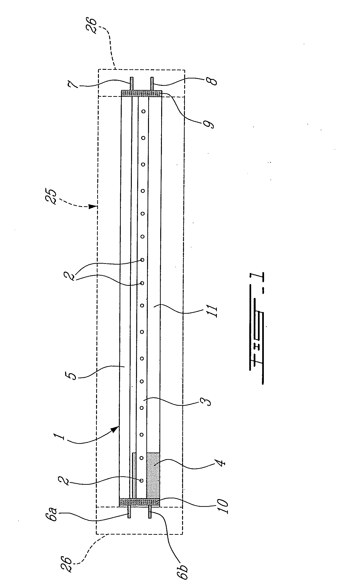
[0041]The present invention discloses two embodiments of an LED lighting device 1 adapted for installation in refrigerated food merchandising display cases as a replacement to a conventional fluorescent lighting fixture tube. The present LED lighting device 1 contains multiple light emitting diodes (LEDs) 2 therein, which provide the desired lighting. FIG. 1 of the drawings illustrate the first embodiment LED lighting device 1 provided with an internal power assembly 4 and as a replacement LED lighting device 1, to a fluorescent tube of an existing conventional fluorescent tube lighting fixture 25.

second embodiment

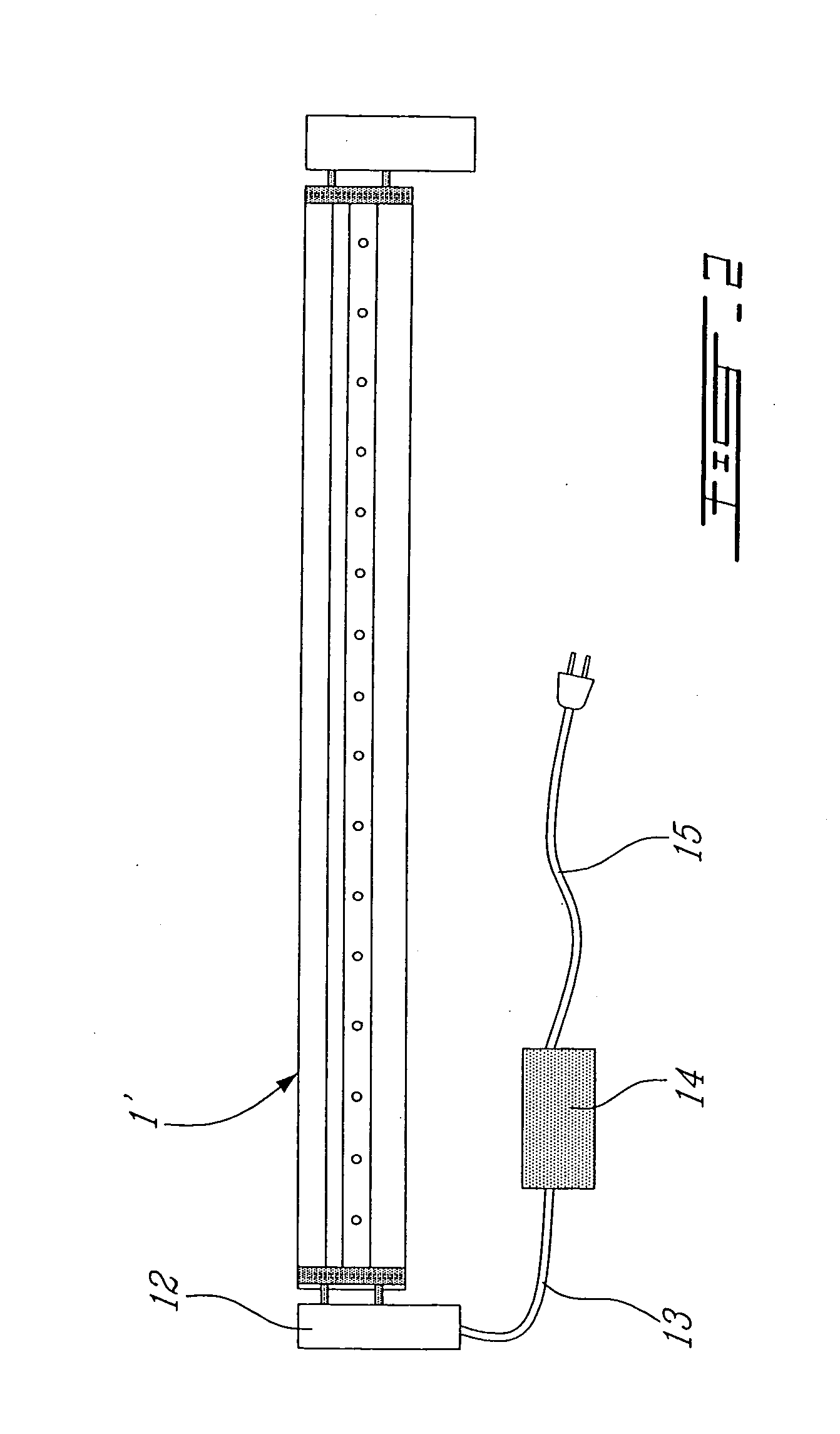
[0042]FIG. 2 illustrate the configuration of the LED lighting device 1′ wherein, the power conversion assembly 14 is installed externally to the LED lighting device by means of a connector 12 and wiring harness 13. Conventional 115 volts AC electrical source is supplied to the power conversion assembly 14 through a connection cable 15 connected to the conventional supply.

[0043]While referring to FIG. 1, the LED lighting device 1 is comprised of an aluminium fixture 5 onto which the other components of the LED lighting device are mounted. An LED printed circuit board 3 is mounted onto the aluminium fixture as to allow a secure connection and to provide a heat sink for the heat generated by the LEDs 2 to flow into the aluminium fixture. The LED lighting device 1 is equipped with connector pins 6a, 6b, 7 and 8 arranged similarly to a fluorescent tube whereby to connect to a fluorescent tube fixture and facilitating its replacement. The connector pins 6a, 6b, 7 and 8 are connected to th...


PUM


Abstract

A multiple LED lighting device and appropriate electrical components integrated into two versions and serving as a direct replacement for conventional fluorescent lighting used in refrigerated food merchandisers. Both versions include appropriate connectors and pins, enabling the LED lighting device to be installed directly in a food merchandising display case lighting fixture. The LED lighting supply circuit may include appropriate electrical components such as rectifiers, step-down transformers, regulators and colour rendering controls to provide the required voltage for the LEDs and appropriate light spectrum. The electrical components may be mounted either integrally within the device, incorporated in an end cap thereof, or installed separately within the refrigerated food merchandising display case. The light may be coloured within the permissible light spectrum by the use of appropriate LEDs and drivers providing the desired coloured lighting.

Description

[0001]This present invention relates to an LED lighting device for use as a replacement of fluorescent lights in a light tube fixtures mounted in refrigerated food display cases and more specifically to an LED lighting device having reduced energy consumption and reduce heat generation.BACKGROUND OF THE INVENTION[0002]For many years the lighting of the interiors of refrigerated food merchandising display cases has been accomplished with the use of fluorescent lighting systems. However, fluorescent lights possess many characteristics which constitute major disadvantages for the food store owners. The disadvantages include the short lifetime of the fluorescent lighting tube, low efficiency at low temperatures approaching freezing temperatures and below freezing temperatures, high power requirements, counter productive heat injection within the refrigerated volume, low durability and high electromagnetic interference which can be detrimental to other electrical systems. In addition, sp...

Claims


Application Information

Patent Timeline
Patent Type & Authority Applications(United States)
IPC IPC(8): F21V19/02F21V11/00
CPCA47F3/001F21K9/00F21V33/0012F21W2131/305F21W2131/405F21V23/06Y02B20/386F21K9/17F21Y2103/003F21V23/023F21Y2101/02F21K9/27F21Y2103/10F21Y2115/10Y02B20/30
Inventor DE CASTRIS, PIERRE
Owner DE CASTRIS PIERRE
Why Eureka
Try Eureka