Lens cap and light emitting diode package structure using the same

a technology of light-emitting diodes and lens caps, which is applied in the direction of lighting and heating apparatus, semiconductor devices for light sources, instruments, etc., can solve the problems of increased production cost and manufacturing time, increased design and manufacturing difficulties, and increased mass production, so as to improve the lateral luminous efficiency of leds and simplify the structure. , the effect of reducing light leakag

Inactive Publication Date: 2008-06-26
IND TECH RES INST
View PDF6 Cites 53 Cited by
  • Summary
  • Abstract
  • Description
  • Claims
  • Application Information

AI Technical Summary

Benefits of technology

[0008]In view of the above problems, the present invention provides a lens cap and a light emitting diode (LED) package structure using ...

Problems solved by technology

Firstly, the incident angle of the light directly projected onto the reflective surface by the light source will change when the incident point is different, so in order to ensure the total reflection to occur on the reflective surface, the profile of curve of the reflective surface must be calculated precisely, which will make the design and manufacturing more difficult.
Secondly, the sawtooth-shaped refractive surf...

Method used


Image

  • Lens cap and light emitting diode package structure using the same
  • Lens cap and light emitting diode package structure using the same
  • Lens cap and light emitting diode package structure using the same

Examples


Embodiment Construction

[0022]The objectives, structures, features, and functions of the present invention will be illustrated in detail below accompanied with the embodiments.

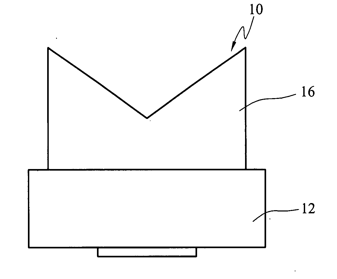
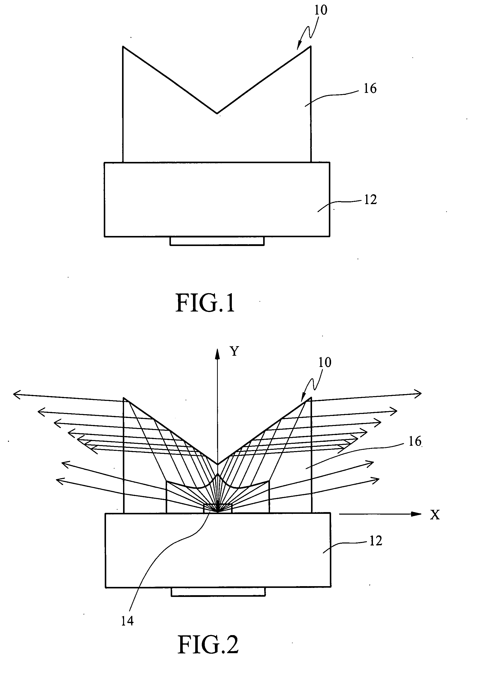
[0023]Referring to FIGS. 1 and 2, a side-emitting light emitting diode (LED) package structure 10 disclosed in a first embodiment of the present invention includes a base 12, an light emitting diode (LED) chip 14, and a cap body 16 of a lens cap. The base 12 supports the LED chip 14, and the LED chip 14 serves as a point light source, so as to emit divergent light to uncertain directions. The cap body 16 of the lens cap is fixed on the base 12, and covered on the LED chip 14, so as to refract the light emitted by the LED, such that the light is projected to the lateral of the lens cap.

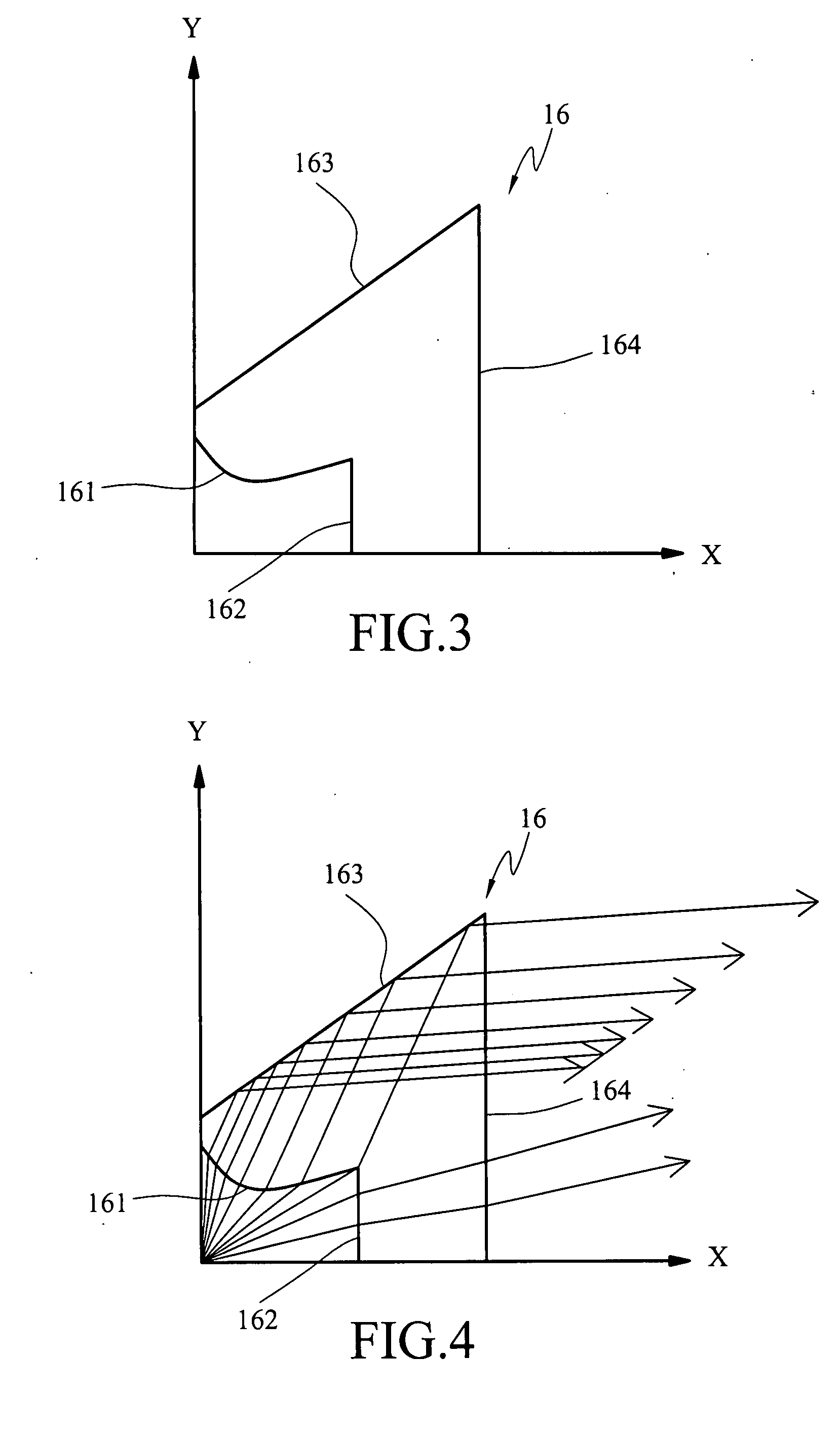
[0024]The cap body 16 is made of a transparent material, and can be an independent component or be formed monolithically with the base 12. The structure of the cap body 16 is an axially symmetric structure about a longitudinal direction Y passing throug...


PUM


Abstract

A lens cap and an LED package structure using the same are provided. The lens cap includes a cap body made of a transparent material for being covered on a point light source. The cap body includes a first incident surface, which is a curved surface raised on a inner side of the cap body and refracts light emitted by the point light source into the cap body. A reflective surface is formed the outer side of the cap body and is opposite to the first incident surface, wherein the reflective surface reflects the light refracted by the first incident surface. A light-transmitting surface is formed on the outer side of the cap body, and the light reflected by the reflective surface is projected onto the light-transmitting surface to exit the cap body. Thus, the light is emitted towards the lateral of the lens cap along a horizontal direction.

Description

CROSS-REFERENCE TO RELATED APPLICATIONS[0001]This non-provisional application claims priority under 35 U.S.C. §119(a) on Patent Application No(s). 095148045 filed in Taiwan, R.O.C. on Dec. 20, 2006, the entire contents of which are hereby incorporated by reference.BACKGROUND OF THE INVENTION[0002]1. Field of Invention[0003]The present invention relates to a side-emitting type light emitting diode (LED) package structure, and more particularly, to a lens cap that refracts light emitted by a point source to lateral side of the lens cap and the LED package structure.[0004]2. Related Art[0005]Currently, light emitting diodes (LEDs) are widely applied to backlight modules of liquid crystal displays (LCDs), especially to that of small-sized LCDs. For example, the LEDs are used in the backlight modules of the LCDs of portable electronic devices or car electronic devices. The LEDs are featured in emitting monochromatic light and act as a point light source, so it is an important task on how...

Claims


Application Information

Patent Timeline
IPC IPC(8): F21V13/04
CPCF21V5/046F21V7/0091F21V13/04F21Y2101/02G02B19/0061H01L33/60G02B19/0071G02B19/0028H01L33/58F21Y2115/10
Inventor YANG, CHENG-LINCHUNG, SHUANG-CHAO
Owner IND TECH RES INST
Why Eureka
Try Eureka