Camera adapter having a camera holder and an optical adapter

Active Publication Date: 2008-06-26
CARL ZEISS SURGICAL
View PDF14 Cites 31 Cited by
  • Summary
  • Abstract
  • Description
  • Claims
  • Application Information

AI Technical Summary

Benefits of technology

[0010]A second object of the invention is to provide an optical adapter that can be used

Problems solved by technology

However, it is not always readily possible to arrange the coupling-out device in the observer's binocular tube.
However, it is not possible to use a coupling-out device in the binocular tube in the case of pivoting tubes.
A TV adapter is highly suitable for recording television images, but is less suitable for use with a digital photographic apparatus.
For example, pupil adaptation is not optimal.
On the other hand, the image quality criteria for high-resolution camera chips in digital photographic apparatuses with TV adapters generally are not met since they are adapted to the resolution of TV cameras, which is considerably lower than that of photographic apparatuses.
In other words, the optics of TV adapters will scarcely meet the demands imposed by a digital photographic apparatus.
Another problem of prior ar

Method used


Image

  • Camera adapter having a camera holder and an optical adapter
  • Camera adapter having a camera holder and an optical adapter
  • Camera adapter having a camera holder and an optical adapter

Examples


first embodiment

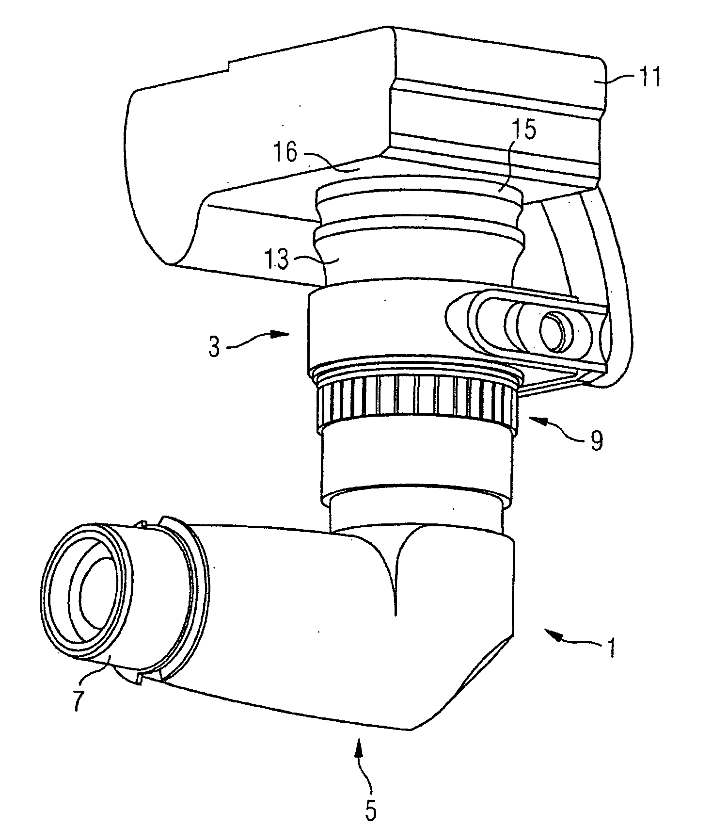
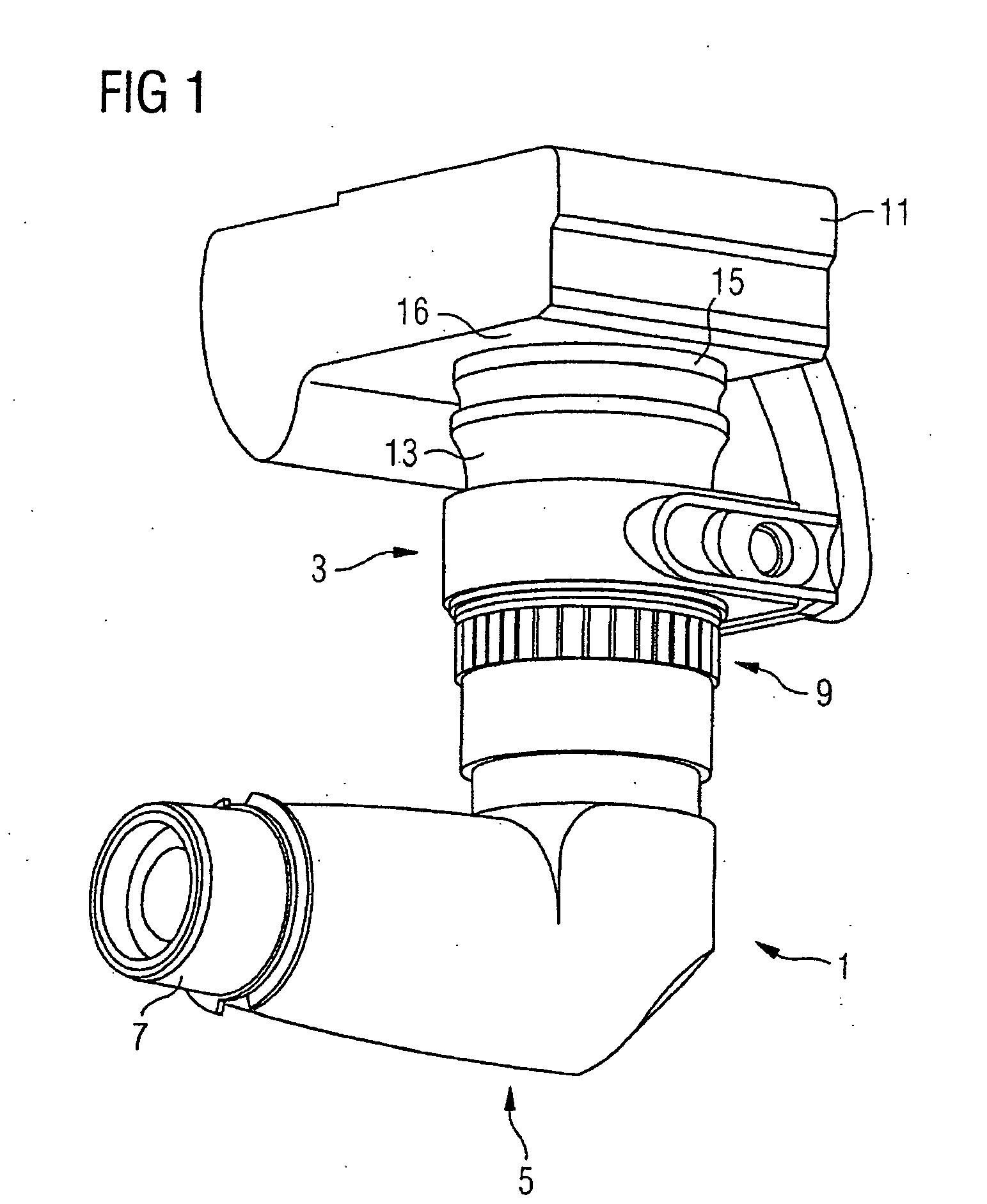
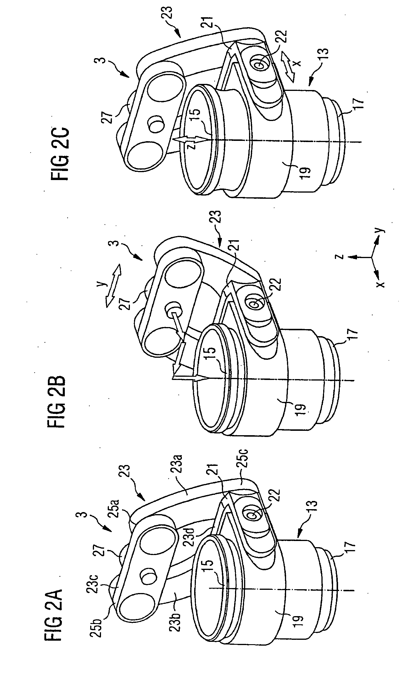
[0037]FIGS. 2A to 2C illustrate the camera holder of the camera adapter 1 in detail, and shows the sleeve 13, the edge 15 and an external thread 17 at the end opposite the edge 15. The external thread 17 defines the mating piece for the union nut of the optical adapter and thus forms the mechanical interface to the optical adapter. A plug-in sleeve or a connector may be provided instead of the external thread.

[0038]The sleeve 13 is surrounded by a clamping ring 19 that is connected to a slide 21. A parallelogram linkage 23 is arranged at that end of the slide 21 that faces away from the clamping ring 19. The linkage 23 includes four lever arms 23a to 23d that are each connected to one another at their ends by rotating joints 25a to 25d. In this case, the lever arm 23d is a crossmember of the slide 21. A screw 27 having a thread that matches the stand thread of a camera is arranged in the center of the lever arm 23c.

[0039]The illustrated construction illustrated in FIGS. 2A-2C makes...

second embodiment

[0042]A camera holder in accordance with the invention is identified by the numeral 103 in FIGS. 3A to 3C. The camera holder 103 comprises a sleeve 113 and a slide 121 fastened to the sleeve 113. The slide 121 has a receptacle 123 for receiving a bracket 125 that is in the form of a segment of a circle. A screw 127 that matches a stand thread of a camera is situated at the outer end of the bracket 125. The bracket 125 has an elongated hole 129 with a curvature that follows the curvature of the bracket 125.

[0043]A threaded pin (not shown) is passed through the elongated hole 129 of the bracket 125 and through the receptacle 122 of the slide 121. The threaded pin and the contour of the elongated hole 129 define a guide system for guiding the bracket 125 through displacement inside the receptacle 123 of the slide 121. The pin axis also constitutes an axis of rotation about which the bracket 125 can be rotated. The bracket 125 can be fixed with respect to the threaded pin using a tensio...

third embodiment

[0046]the camera holder is described below with reference to FIGS. 4A to 4C. This embodiment is very similar to the embodiment of FIGS. 3A to 3C. Elements in both embodiments are denoted by the same reference numerals in FIGS. 3A to 3C and 4A to 4C.

[0047]The camera holder 203 of the third embodiment comprises a sleeve 113 with an attachment 215 that has a receptacle 217. A pin 219 is pivotably mounted in the receptacle 217. The pivot axis of the pin 219 is parallel to the central axis of the sleeve 113. The pin 219 extends through an elongated hole 129 of a curved bracket 125. As in the second exemplary embodiment, the elongated hole 129 has a curvature that follows the curvature of the bracket 125. In this case too, a straight bracket with a straight elongated hole can be used instead of a curved bracket with a curved elongated hole.

[0048]As in the second embodiment, the screw 127 and a camera fastened to the screw 127 can be moved in the region of an annular surface in the third e...


PUM


Abstract

A camera holder (3) is provided for fixing a camera (11) or a camcorder to an optical observation device. The holder (3) has a variable-length sleeve (13) with a first end configured to receive the camera objective and a second end configured to secure the sleeve (13) relative to the optical observation device. The holder (3) also has an adjusting device (19) fixed to the sleeve (13). The adjusting device (19) has a pin for connection with a stand mating thread of a camera (11) and is configured to compensate for an offset between the stand mating thread and the camera objective. The adjusting device (19) enables the camera (11) to be positioned with respect to the sleeve and the optical observation device.

Description

BACKGROUND OF THE INVENTION[0001]1. Field of the Invention[0002]The invention relates to a camera adapter having a camera holder and an optical adapter as well as to the camera holder and the optical adapter themselves.[0003]2. Description of the Related Art[0004]Special phototubes that have a coupling-out device in the observer's binocular tube for photographic recordings are used in microscopy. However, it is not always readily possible to arrange the coupling-out device in the observer's binocular tube. For example, pivoting tubes often are used in microsurgery to adapt a surgical microscope ergonomically to the surgical situation. However, it is not possible to use a coupling-out device in the binocular tube in the case of pivoting tubes. Therefore, a compromise usually is selected at present for stereomicroscopes, for instance surgical microscopes, namely a so-called TV adapter which is provided with additional optics. This adapter is adapted to a coupling-out device in the reg...

Claims


Application Information

Patent Timeline
IPC IPC(8): G03B17/00
CPCG02B21/362G03B17/56G03B17/14G03B17/565G03B17/566
Inventor GARTNER, HARTMUTKOCH, WERNERROBRA, WOLFGANGLUCKE, CHRISTIANRIETH, KARSTEN
Owner CARL ZEISS SURGICAL
Why Eureka
Try Eureka