Battery pack and battery module and method for operating a battery module

a battery module and battery pack technology, applied in secondary cell servicing/maintenance, cell components, instruments, etc., can solve the problems of space-saving design of connecting cell connectors, and achieve the effect of reducing the fuel consumption of hybrid vehicles, and being effective and non-destructiv

Active Publication Date: 2008-06-26
ROBERT BOSCH GMBH
View PDF8 Cites 53 Cited by
  • Summary
  • Abstract
  • Description
  • Claims
  • Application Information

AI Technical Summary

Benefits of technology

[0009]It is provided that a cell connector for electrically connecting the cells is provided on at least two cells, on the end face on the same side relative to their position in the battery pack, the cell connector connecting one pole of the connected cells and extending to a contact region of a circuit board. The cell bodies of the cells are positioned parallel to each other, and the end faces of the cell bodies are located in the same plane. The cell connectors may be contacted directly with the circuit board. As a result, a defined—for fabrication purposes—geometric assignment of the ends of the cell connectors to the circuit board side and of the position of the circuit board is made possible, thereby enabling and simplifying an automated fabrication process. This makes it possible to shorten cycle times in the fabrication of battery packs.
[0028]A preferred use of the inventive battery module in hybrid vehicles makes it possible to recharge the battery pack—in an effective and non-destructive manner—at a mains outlet or, e.g., at solar cell-operated recharging stations at parking lots, company parking lots in particular. Since most vehicles are operated for short periods of time and remain in the same location for a long 10 time before use, it is possible and practical to recharge the battery module, in particular with advantageously stationary solar panels, thereby reducing the fuel consumption of the hybrid vehicle considerably.

Problems solved by technology

This results in a particularly space-saving design for connecting the cell connectors.

Method used


Image

  • Battery pack and battery module and method for operating a battery module
  • Battery pack and battery module and method for operating a battery module
  • Battery pack and battery module and method for operating a battery module

Examples


Embodiment Construction

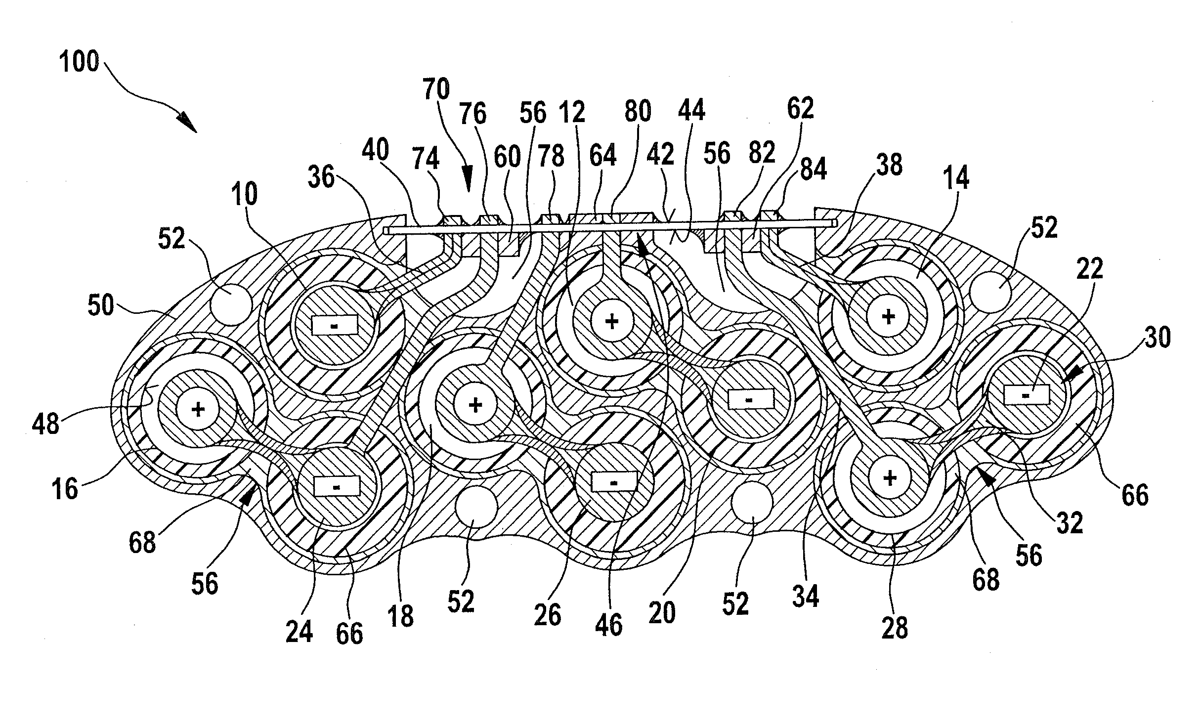
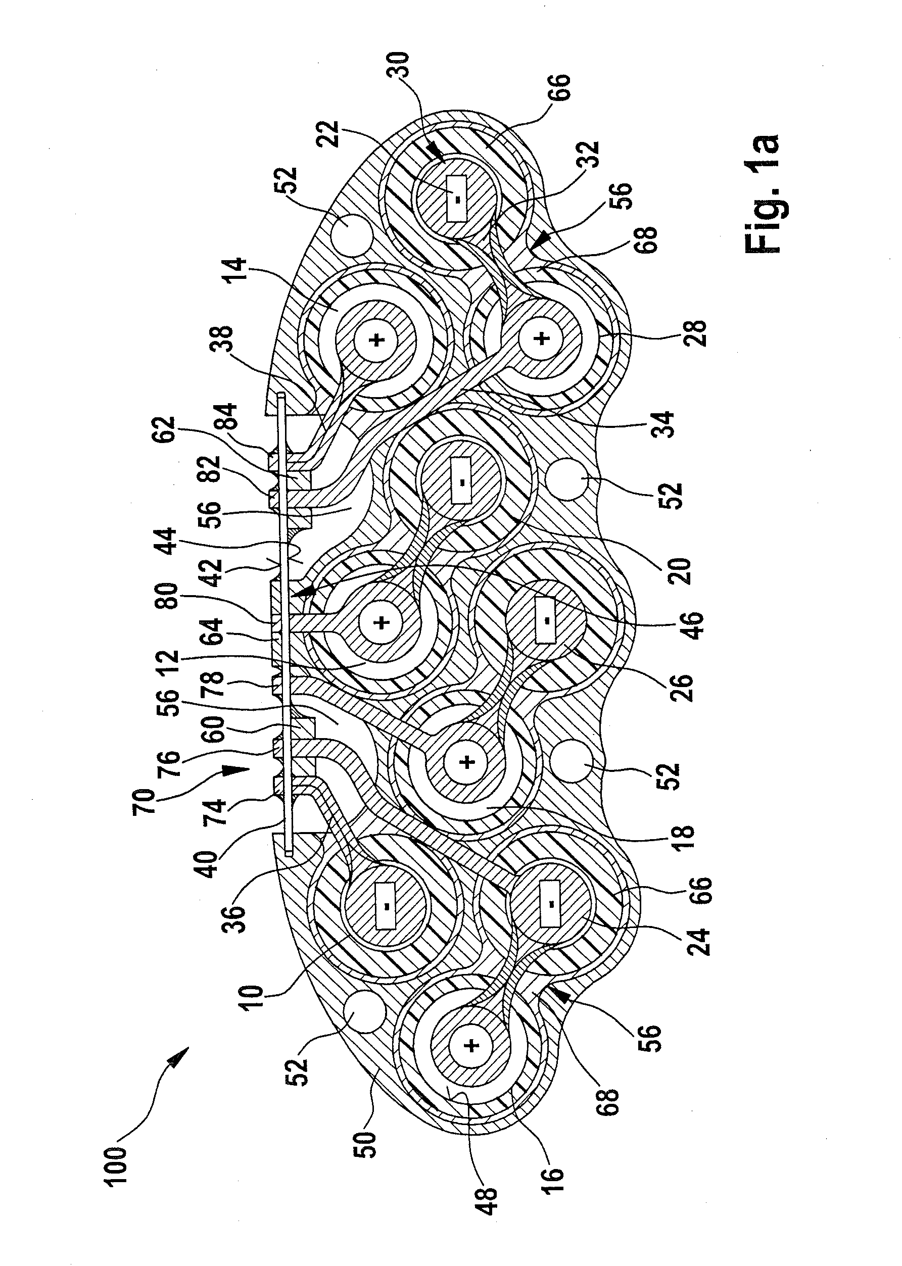
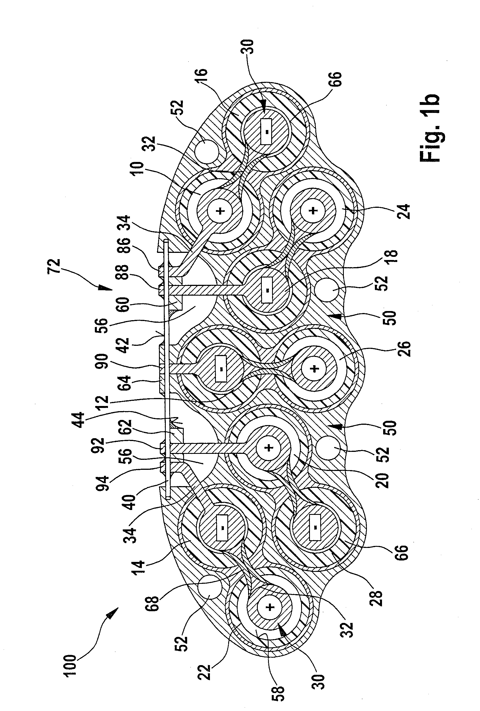
[0036]Components that are the same or similar are labelled with the same reference numerals in the figures. FIGS. 1a and 1b explain the present invention with reference to a top view of a top side (FIG. 1a) and an underside (FIG. 1b) of a preferred battery pack 100. Battery pack 100 includes, e.g., ten cylindrical cells 10, . . . , 28, in a hexagonal configuration, which enables cells 10, . . . , 28 to be packed as tightly as possible. Depending on the need, more or fewer cells may be provided, and the cells may be positioned in any configuration required.

[0037]Cells 10, . . . , 28 preferably have the same design and are oriented antiparallel relative to each other, as depicted schematically in FIG. 3 based on two cells; the antiparallel orientation is not labeled separately. As a result, a longitudinal extension 98 of one cell body 96 is oriented parallel to longitudinal extension 98 of adjacent cell body 96. Electrical positive pole 96a of one cell 96 points toward the same side a...


PUM

PropertyMeasurementUnit
voltageaaaaaaaaaa
voltageaaaaaaaaaa
output voltagesaaaaaaaaaa

Abstract

A battery pack with at least two electrochemical cells, lithium ion cells in particular, has each cell including a positive pole and a negative pole on the end face of the particular cell body, the poles of the cells being electrically connected in series and / or in parallel. A cell connector for electrically connecting the cells is provided on at least two cells, on the end face on the same side relative to their position in the battery pack, the cell connector connecting one pole of the connected cells and extending to a contact region of a circuit board; the cell bodies of the cells are positioned parallel to each other, and the end faces of the cell bodies are located in the same plane.

Description

CROSS-REFERENCE TO A RELATED APPLICATION[0001]The invention described and claimed hereinbelow is also described in German Patent Application DE 102006061270.1 filed on Dec. 22, 2006. This German Patent Application, whose subject matter is incorporated here by reference, provides the basis for a claim of priority of invention under 35 U.S.C. 119(a)-(d).BACKGROUND OF THE INVENTION[0002]The present invention is directed to a battery pack and a battery module, and a method for operating a battery module.[0003]It is known that the service life of lithium ion secondary battery cells is affected by excessive discharging and by overcharging. To prevent damage, these battery cells should be charged to a maximum voltage in the range of 4.0 to 4.5 V, and they should not fall below a voltage of 1.0 to 2.5 V.[0004]If several cells are connected in a series connection to form a “battery pack”, it is not sufficient to monitor the voltage of the entire pack. Due to production-related scatterings of...

Claims


Application Information

Patent Timeline
Patent Type & Authority Applications(United States)
IPC IPC(8): H01M10/48H02J7/00H01M10/36H01M2/20H01M50/529H01M10/0525H01M50/213H01M50/224H01M50/227H01M50/247H01M50/51H01M50/512H01M50/516H01M50/519
CPCH01M2/1022Y02T10/7011H01M2/202H01M6/42H01M10/0525H01M10/425H01M10/482H01M10/5004H01M10/5008H01M10/5014H01M10/5016H01M10/503H01M10/504H01M10/5089H01M2/1077H01M10/625H01M10/653H01M10/643H01M10/617H01M10/6235H01M10/613H01M10/659Y02E60/10H01M50/519H01M50/224H01M50/247H01M50/512H01M50/51H01M50/227H01M50/516H01M50/213
Inventor SEILER, HARTMUTKOHLRAUSCH, PHILIPP
Owner ROBERT BOSCH GMBH
Why Eureka
Try Eureka