Hybrid optical head for direct engraving of flexographic printing plates

a printing plate and optical head technology, applied in the field of optical printing head and direct engraving of flexographic printing plates, can solve the problem of significantly higher cost per watt of output optical power of broad spot lasers

Active Publication Date: 2008-06-26
MIRACLON CORP
View PDF16 Cites 57 Cited by
  • Summary
  • Abstract
  • Description
  • Claims
  • Application Information

AI Technical Summary

Benefits of technology

[0013]In particular, system for engraving flexographic printing plates, comprises a first group of one or more radiation sources each emitting radiation having substantially the same intensity; a first one or more optical elements coupled to the first group of one or more radiation sources for imaging the radiation emitted from the first group of one or more radiation sources onto a flexographic printing plate; a second group of one or more radiation sources each emitting radiation having substantially the same intensity; and a second one or more optical elements coupled to the second group of one or more radiation sources for imaging the radiation emitted from the second group of one or more radiation sources onto the flexographic printing plate, wherein the intensity and spot size of the first group of one or more radiation sources is different from the intensity and spot size of the second group of one or more radiation sources, and wherein the first and second groups of radiation sources operate simultaneously.
[0014

Problems solved by technology

Although high power density does not necessary conflict with laser focusability, from a practical perspect

Method used


Image

  • Hybrid optical head for direct engraving of flexographic printing plates
  • Hybrid optical head for direct engraving of flexographic printing plates
  • Hybrid optical head for direct engraving of flexographic printing plates

Examples


Embodiment Construction

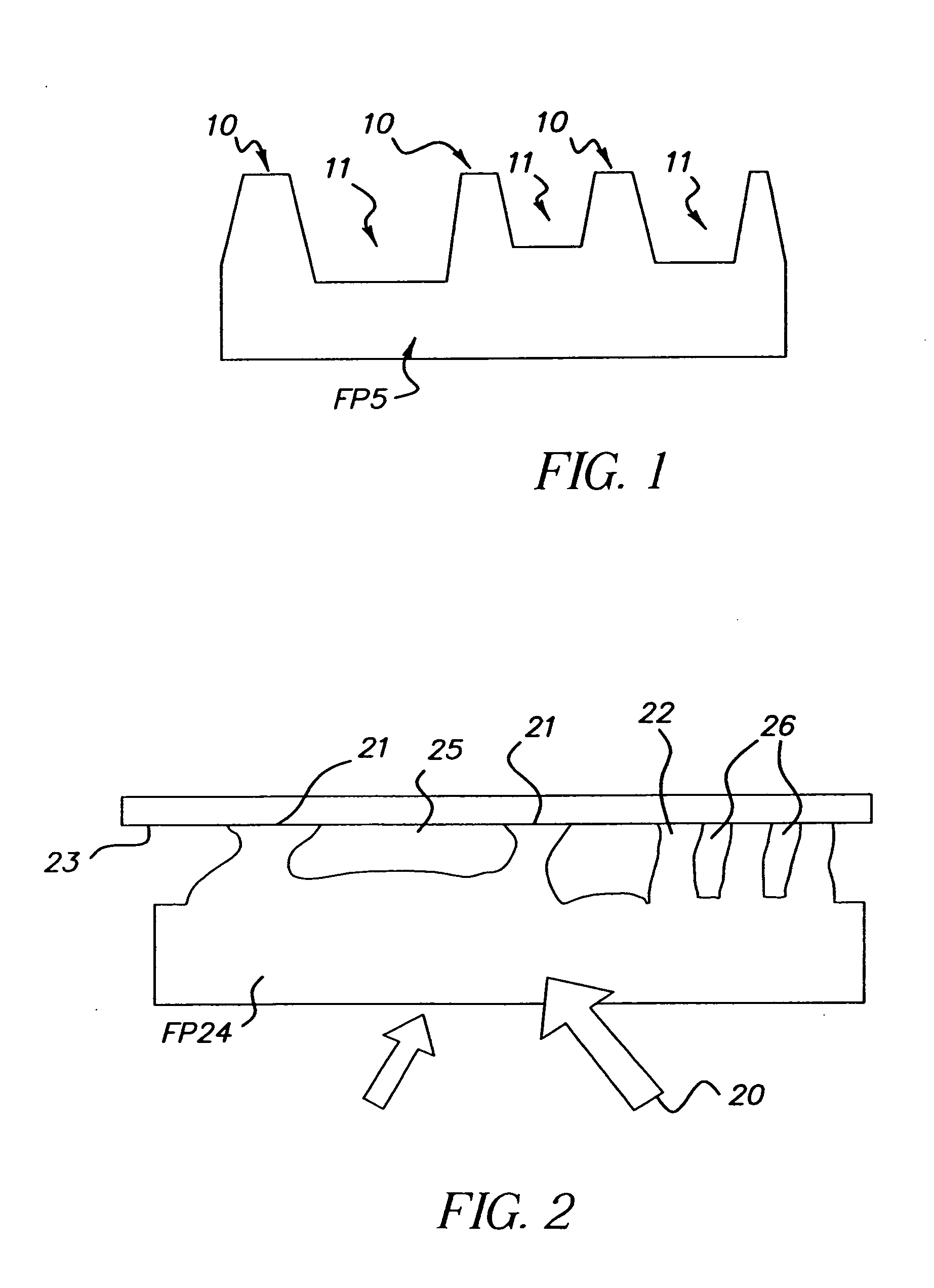
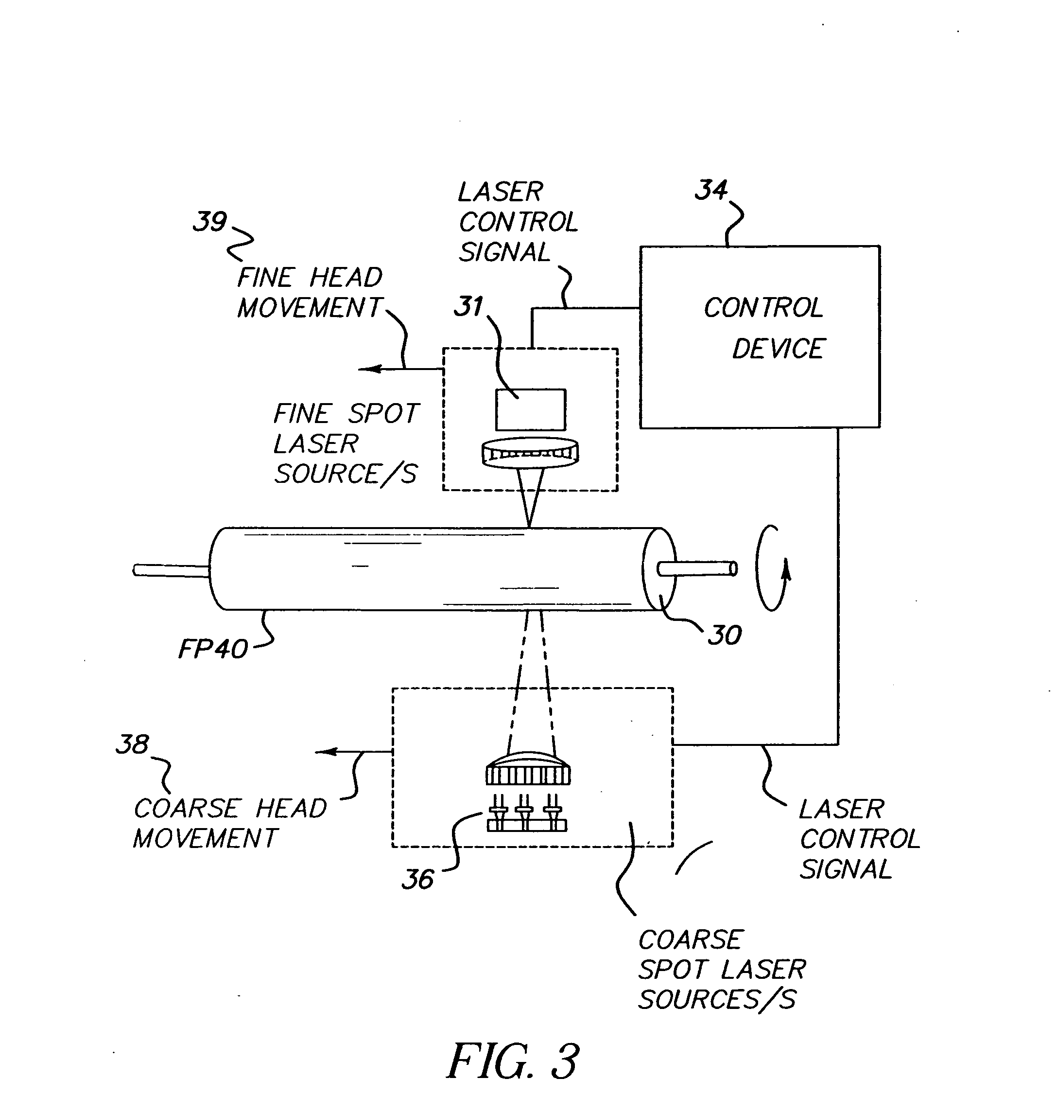
[0027]The combination of radiation sources with high power broad spots and low power fine spots, referred to as a Hybrid Optical Head System (HOHS), is well suited for 3-D processing of direct engraving flexography applications. Referring to FIG. 1, because a flexographic plate (FP) 5 is pressed directly onto printed media, such as, for example, paper, packaging material and the like (not shown), areas 10 that transfer ink to the printed media need to be elevated from blank areas 11 which do not transfer ink. The required depth of the blank areas 11 is such that when the FP 5 is pressed against another surface, the blank areas 11 should be kept out of contact with the surface.

[0028]Referring to FIG. 2, FP 24 is being pressed firmly against contact surface 23 by pressure 20. Because FP 24 is deformable, imaging features 21 separated by large blank area 25 (typically used to produce large solid areas in imaging) will be deformed more strongly and pushed closer to contact surface 23 th...


PUM

PropertyMeasurementUnit
Optical propertiesaaaaaaaaaa

Abstract

An optical imaging head for direct engraving of flexographic printing plates, comprising: at least two groups of radiation sources, each group comprising at least one radiation source, wherein the radiation sources within each group emit radiation having the same intensity and spot size, different from the intensity and spot size of radiation sources in the other groups, said groups of radiation sources operating simultaneously.

Description

CROSS REFERENCE TO RELATED APPLICATIONS[0001]Reference is made to commonly-assigned copending U.S. patent application Ser. No. 11 / 353,217, filed Feb. 13, 2006, entitled FLEXOGRAPHIC PRINTING PLATE PRECURSOR AND IMAGING METHOD, by Kimelblat et al., the disclosure of which is incorporated herein.FIELD OF THE INVENTION[0002]This invention relates to an optical printing head and methods for direct engraving of flexographic printing plates.BACKGROUND OF THE INVENTION[0003]Direct engraving of a flexography plate requires carving three dimensional (3-D), on plate material, directly with a laser system. This is remarkably different from two dimensional (2-D) imaging techniques that require post processing steps to produce the 3-D features.This difference introduces several challenges for the laser imaging system:[0004]1. The laser system must have sufficient power to ablate the material; and[0005]2. The laser spot should be small enough to achieve the fine detail required in quality printin...

Claims


Application Information

Patent Timeline
IPC IPC(8): G03F7/20G21G4/00
CPCB41C1/05B23K26/06B23K26/08
Inventor SIMAN-TOV, ALONCHAYET, HAIM
Owner MIRACLON CORP
Why Eureka
Try Eureka