Three-dimensional multi-shaft interlocked numerical controlled engraving and milling device

A multi-axis linkage, engraving and milling machine technology, applied in the direction of milling machines, milling machine equipment, metal processing machinery parts, etc., can solve the problem of not being able to finish the products with large shapes and complex shapes, and achieve the effect of high processing level

Inactive Publication Date: 2009-07-29
袁焕春 +1
View PDF1 Cites 20 Cited by
  • Summary
  • Abstract
  • Description
  • Claims
  • Application Information

AI Technical Summary

Problems solved by technology

[0003] The purpose of the present invention is to solve the technical problem that the existing CNC engraving and milling technology cannot finish machining large and complex products, and to provide a three-dimensional multi-axis CNC engraving and milling equipment capable of engraving and milling large and complex products

Method used


Image

  • Three-dimensional multi-shaft interlocked numerical controlled engraving and milling device
  • Three-dimensional multi-shaft interlocked numerical controlled engraving and milling device
  • Three-dimensional multi-shaft interlocked numerical controlled engraving and milling device

Examples


Embodiment 1

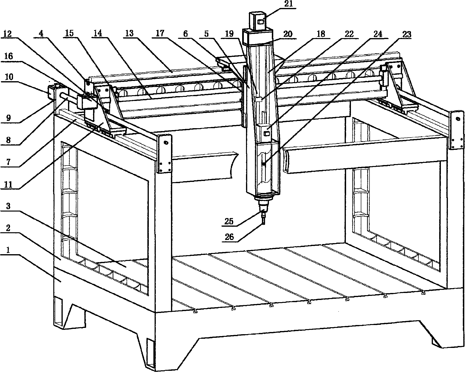
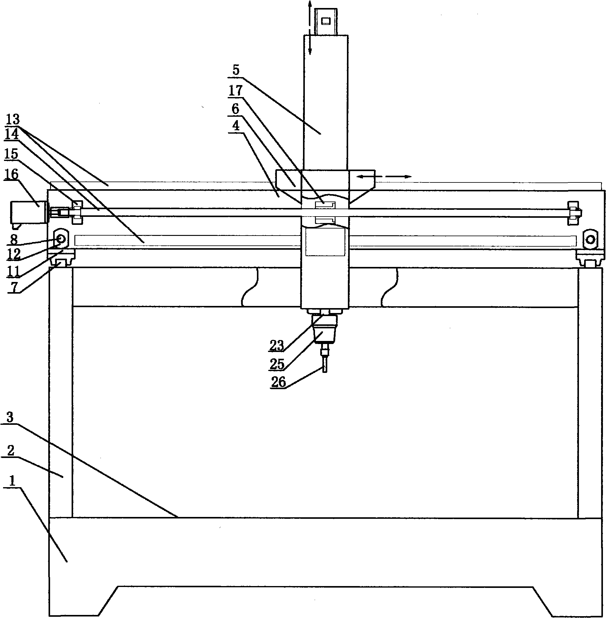
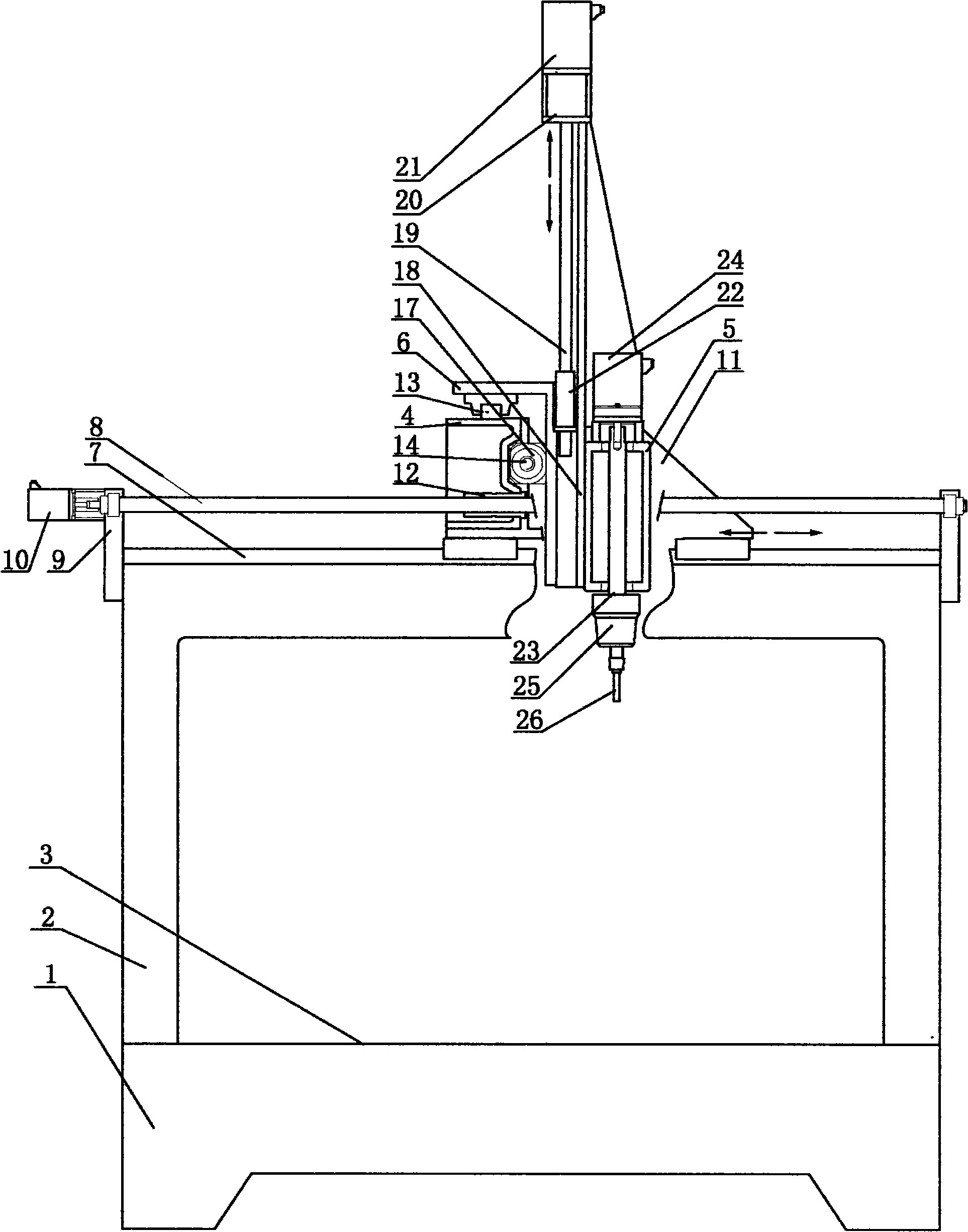
[0016] Such as figure 1 --The three-dimensional multi-axis linkage CNC engraving and milling machine of the present invention shown in 4 is a three-dimensional three-axis linkage CNC engraving and milling machine, which includes: machine base 1, body 2, worktable 3, working beam 4, Z The axial body 5, the Z axial body support 6 and the numerical control unit for controlling the work of the machine tool. Its specific structure is as follows:

[0017] (1) The fuselage 2 is a frame structure, which is composed of four columns, two left and right longitudinal beams, and two front and rear transverse beams. A Y-axis linear guide rail 7 is installed on the two longitudinal beams of the fuselage 2. The Y-axis guide rail 7 on one side or both sides of the body is provided with a drive device y, and the drive device y includes: a ball screw y8, and two screw supports 9 arranged at both ends of the Y-axis guide rail 7 for supporting the ball screw 8 , and the servo motor y10 matched w...

Embodiment 2

[0023] Such as Figure 5 --The three-dimensional multi-axis linkage CNC engraving and milling machine of the present invention shown in 6 is a three-dimensional five-axis linkage CNC engraving and milling machine, which is based on the three-dimensional three-axis linkage CNC engraving and washing machine. 5, and the Z axis body 5 is provided with an A-axis that can rotate horizontally and circularly, and a C-axis that can rotate vertically and circularly is provided on the A-axis, and the cutter device is arranged on the C-axis. It includes: a machine base 1, a fuselage 2, a worktable 3, a working beam 4, a Z-axis body 5, a Z-axis body support 6 and a numerical control unit for controlling the work of the machine tool. Its specific structure is as follows:

[0024] (1) The fuselage 2 is a frame structure, which is composed of four columns, two left and right longitudinal beams, and two front and rear transverse beams. A Y-axis linear guide rail 7 is installed on the two long...


PUM


Abstract

The invention relates to a three-dimensional multishaft ganged digital control engraving and milling machine, which is particularly suitable for performing cutting and engraving and milling processing on large nonmetallic products. The three-dimensional multishaft ganged digital control engraving and milling machine comprises a stand, a body, a work table, a working beam, a Z axial body, a Z axial body support and a digital control unit which is used for controlling the operation of a machine tool, wherein the working beam is connected with the body through a Y axial guide rail and driven by a drive unit to move along a Y axis; the Z axial body support is connected with the working beam through a Z axial guide rail and driven by a drive unit to drive the Z axial body to move along an X axis; the Z axial body is connected with the Z axial support through the Z axial guide rail and driven by a drive unit to move along a Z axis; the body is set to have a frame structure; a Y axial guide rail is arranged on two longitudinal beams of the body respectively; the working beam and a longitudinal beam of the stand form guide rail connection through a beam support; an A axis is arranged on the Z axial body and can perform horizontal and circumferential rotation when being driven by a drive unit; and a C axis is arranged on the A axis and can perform perpendicular and circumferential rotation when being driven by a drive unit. The three-dimensional multishaft ganged digital control engraving and milling machine can implement engraving and milling processing on three-dimensional five axes of the large products when the digital control unit controls various drive units, and the processing level of the machine tool is higher.

Description

technical field [0001] The invention relates to a three-dimensional multi-axis linkage numerical control engraving and milling machine, in particular to a three-dimensional multi-axis linkage numerical control engraving and milling machine used for cutting and engraving and milling of large-scale plastic, foam, wood and other non-metallic products. technical background [0002] Chinese patent CN 2894903Y discloses a utility model patent titled "Numerical Control Engraving and Milling Machine". , beam, connecting plate, slide plate and CNC unit, the workbench is on the bed, the left and right columns are respectively set on both sides of the bed, the beam moving along the Y axis is set on the right column and driven by the driving device, along the X axis The moving connecting plate is set on the crossbeam, the sliding plate fed along the Z axis is set on the connecting plate, and the numerical control unit is connected with each component separately.” This utility model adop...

Claims


Application Information

Patent Timeline
Patent Type & Authority Applications(China)
IPC IPC(8): B23C1/06B23Q1/01B23Q1/25
Inventor 袁焕春潘震州高斌郭圣浩陈世民柯益荣范家华袁晓磊杨泽成
Owner 袁焕春
Why Eureka
Try Eureka