Unlock instant, AI-driven research and patent intelligence for your innovation.

Delivery device for a fluid

Inactive Publication Date: 2008-06-26
BETA MICROPUMP PARTNERS
View PDF5 Cites 0 Cited by
  • Summary
  • Abstract
  • Description
  • Claims
  • Application Information

AI Technical Summary

Benefits of technology

[0009]The delivery device of the invention has the advantage that it can be made with a compact shape through the use of ambient fluid to displace the primary fluid from its reservoir.
[0011]Preferably, the chamber for the ambient fluid extends coaxially with the reservoir inside the housing. This can help to make the device of the invention compact.
[0014]It can also be preferred for the reservoir to be located within the chamber, for example in which the chamber is annular when viewed in cross-section along the axis of the device. Delivery of the ambient fluid to the chamber will then involve the internal wall of the chamber being driven inwardly into the reservoir, to displace primary fluid from the reservoir. This can have the advantage that, when the chamber is annular and surrounds the reservoir (in a coaxial sense), the outlet from the reservoir can be located on or close to the axis of the device.
[0015]Arrangements of the reservoir and the chamber which are not coaxial are also envisaged. For example, the reservoir might be provided towards one end of the housing and the chamber towards the opposite end. The chamber might then expand towards the said opposite end of the housing to cause primary fluid in the reservoir to be displaced. Such a chamber might be defined by a piston which can be displaced along the length of the housing. Such a chamber might be defined by a deformable membrane, for example in the form of an expandable balloon. The use of a deformable membrane has the advantage compared with a displaceable piston that expansion of the chamber does not require frictional forces to be overcome.
[0017]A deformable membrane can deform as a result of a folded construction, by which its configuration can change on deformation into the reservoir by opening of folds, for example relying on an effect which is similar to that which is referred to as a concertina effect. This has the advantage that expansion of the chamber by means of driven ambient fluid does not require that the deformation forces of an elastomeric material have to be overcome.

Problems solved by technology

However, once implanted, the rate of flow of drug through the membrane cannot readily be adjusted.

Method used


Image

  • Delivery device for a fluid
  • Delivery device for a fluid
  • Delivery device for a fluid

Examples


Embodiment Construction

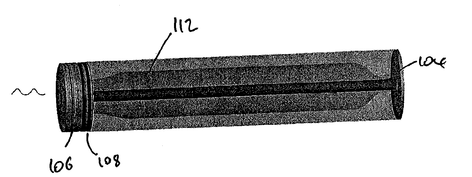
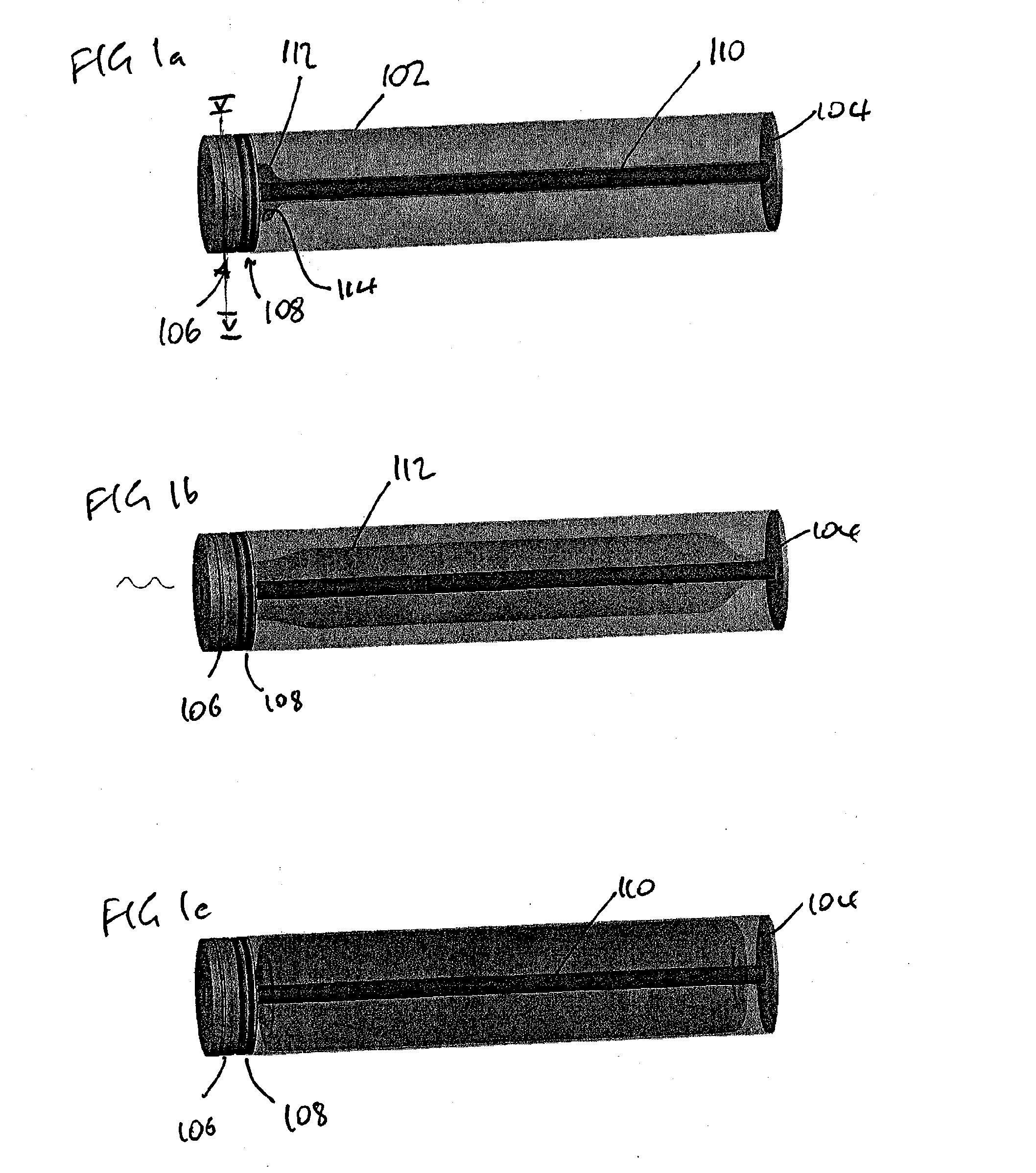
[0036]FIGS. 1a to 1c show a delivery device which makes use of ambient fluid to displace a drug or other primary fluid from a chamber.

[0037]The delivery device comprises a tubular housing having an outer wall 102 which is circular when viewed in cross-section along its length. The diameter of the housing is 1.0 mm, and its length is 10 mm. The housing is formed from a polymeric material such as a poly-propylene. The side wall is formed by extrusion, allowing the volume of the housing to be determined by cutting the extrusion to length. The construction of the end walls is discussed below. They are sealed to the side wall by means of an adhesive.

[0038]The housing is closed at the outlet end of the housing with a simple end wall 104 which is provided by a plain sheet of polymeric material.

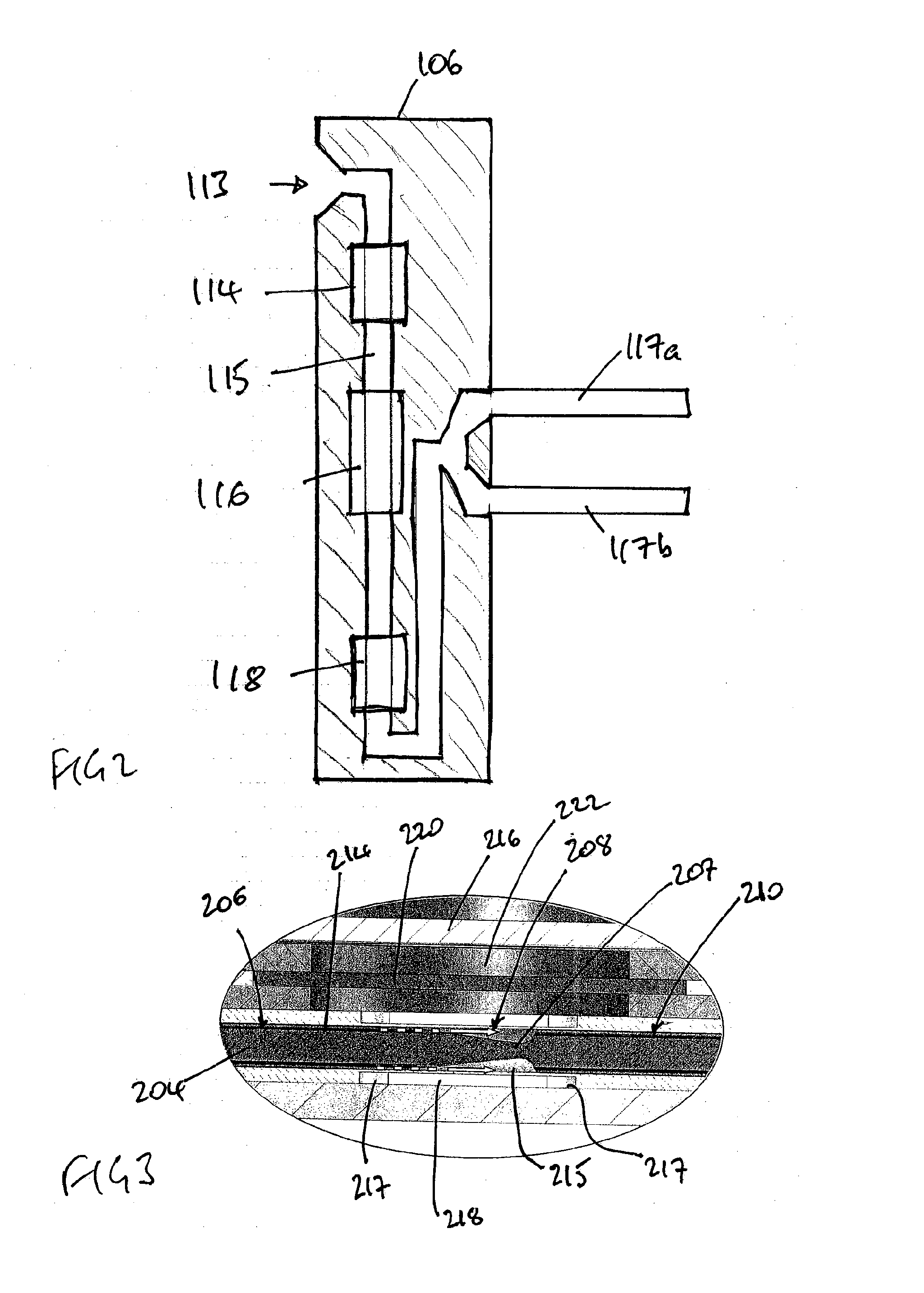
[0039]The housing is closed at its other end by a pair of functional end walls. A first end wall is a pump end wall 106 which is used to drive displacement fluid into the device to cause a primary fl...


PUM


Abstract

A delivery device for a primary fluid includes an elongate tubular housing containing a reservoir for the primary fluid and a chamber for an ambient fluid to which the exterior of the delivery device is exposed. The device includes an outlet from the reservoir for the primary fluid and a device for driving ambient fluid under pressure into the chamber so as to expand the chamber and to cause primary fluid in the reservoir to be displaced towards the outlet. The inlet to the driver device communicates with an opening which is exposed to the ambient fluid to which the exterior of the delivery device is exposed.

Description

BACKGROUND TO THE INVENTION[0001]This invention relates to a delivery device for a fluid.[0002]The flow of fluids through conduits can be controlled using components such as pumps and valves. Pumps and valves can operate to control parameters such as flow rate; adjustment of relative flow rates of constituents in a mixture can be used to vary the composition of the mixture.[0003]Accurate control of flow of a fluid can be important in many medical applications, for example in drug delivery and in the modulation of body fluid drainage. Devices in which flow control is important include pumps for dispensing drugs such as insulin and opiates, and hydrocephalus shunts for drainage of spinal fluids.[0004]Accurate control over the flow of drugs and fluids in medical applications can help to minimise complications in the patient treatment, especially if controlled quantities of drugs can be supplied locally to an affected site. Accurate control can help to optimise efficacy of an administer...

Claims


Application Information

Patent Timeline
IPC IPC(8): A61K9/22A61M5/148
CPCA61M5/1483A61M2005/14513A61M5/16881
Inventor KRUMME, JOHN
Owner BETA MICROPUMP PARTNERS
Features
  • R&D
  • Intellectual Property
  • Life Sciences
  • Materials
  • Tech Scout
  • Unparalleled Data Quality
  • Higher Quality Content
  • 60% Fewer Hallucinations
Learn More