Lathe

a technology of lathes and chucks, applied in the field of lathes, can solve the problems of inability to meet the required product quality in terms of machining precision, workpiece w cannot be held, workpiece w is curved or elastically deformed, etc., and achieves the effect of reducing restoring the pressure of hydraulic oil in the enclosed space, and facilitating retraction

Inactive Publication Date: 2008-07-03
DMG MORI CO LTD
View PDF4 Cites 3 Cited by
  • Summary
  • Abstract
  • Description
  • Claims
  • Application Information

AI Technical Summary

Benefits of technology

[0027]When the first piston is moved by the bias canceling mechanism to the rear end side of the inserting member against a biasing force of the first spring body, the pressure of the hydraulic oil in the enclosed space is decreased. When the pressure is lowered than that of an atmospheric pressure, it is probable that air may flow into the enclosed space from a gap between the piston section of the contact member and the cylinder holes. Therefore, according to the above-described arrangement, when the first piston is biased by the first spring body, and as a result, the first piston is moved to the distal end side of the inserting member, the distal end side of the second piston is pressed by the hydraulic oil and biased by the second spring body as well, thereby positioning the second piston to the rear end side of the first piston in the pressure adjusting space. However, when the first piston is moved by the bias canceling mechanism to the rear end side of the inserting member against the biasing force of the first spring body, the rear end side of the second piston is pressed by the air corresponding to a decrease in pressure of the hydraulic oil. Thereby, the second piston is moved to the distal end side of the first piston in the pressure adjusting space against the biasing force of the second spring body. As a result, the pressure of the hydraulic oil in the enclosed space is restored. This prevents the pressure of the hydraulic oil from becoming negative, whereby above-described inconvenience can be effectively prevented from occurring.
[0028]It may be configured such that each of the contact members is each formed on a distal end surface in the protrusion direction with a groove in parallel with a plane orthogonal to the rotational center axis, the holding mechanism further comprises a returning member which is made of an elastic body formed to be annularly or C-shaped, of which axis line is provided parallel to the rotational center axis, and which is engaged with the groove of each of the contact members, and the returning member deforms elastically to permit a protrusion of each of the contact members and retracts each of the contact members by a shape recovery effect.
[0029]In this way, each of the contact members protruded by the drive mechanism can be easily retracted by the returning member, and thus, it is favorable when the distal end of the inserting member inserted into the interior of the other end side of the workpiece is removed from the workpiece.
[0030]As described above, according to a lathe of the present invention, it is possible to hold a workpiece without elastically deforming it, and to machine with high precision an outer circumferential surface of the workpiece even in the case of a workpiece of which axis line is curved, and thus, it is possible to increase accuracy of straightness, circularity, cylindricity, or the like, for example.

Problems solved by technology

Thus, it is not possible to satisfy a required product quality in terms of machining precision such as straightness, circularity, cylindricity, or the like.
As a result, there arises a problem in that the workpiece W cannot be held.
Further, when the workpiece W is forcedly held, a problem occurs in which the workpiece W is curved or the workpiece W is elastically deformed as in the case described above.

Method used


Image

  • Lathe
  • Lathe
  • Lathe

Examples


Embodiment Construction

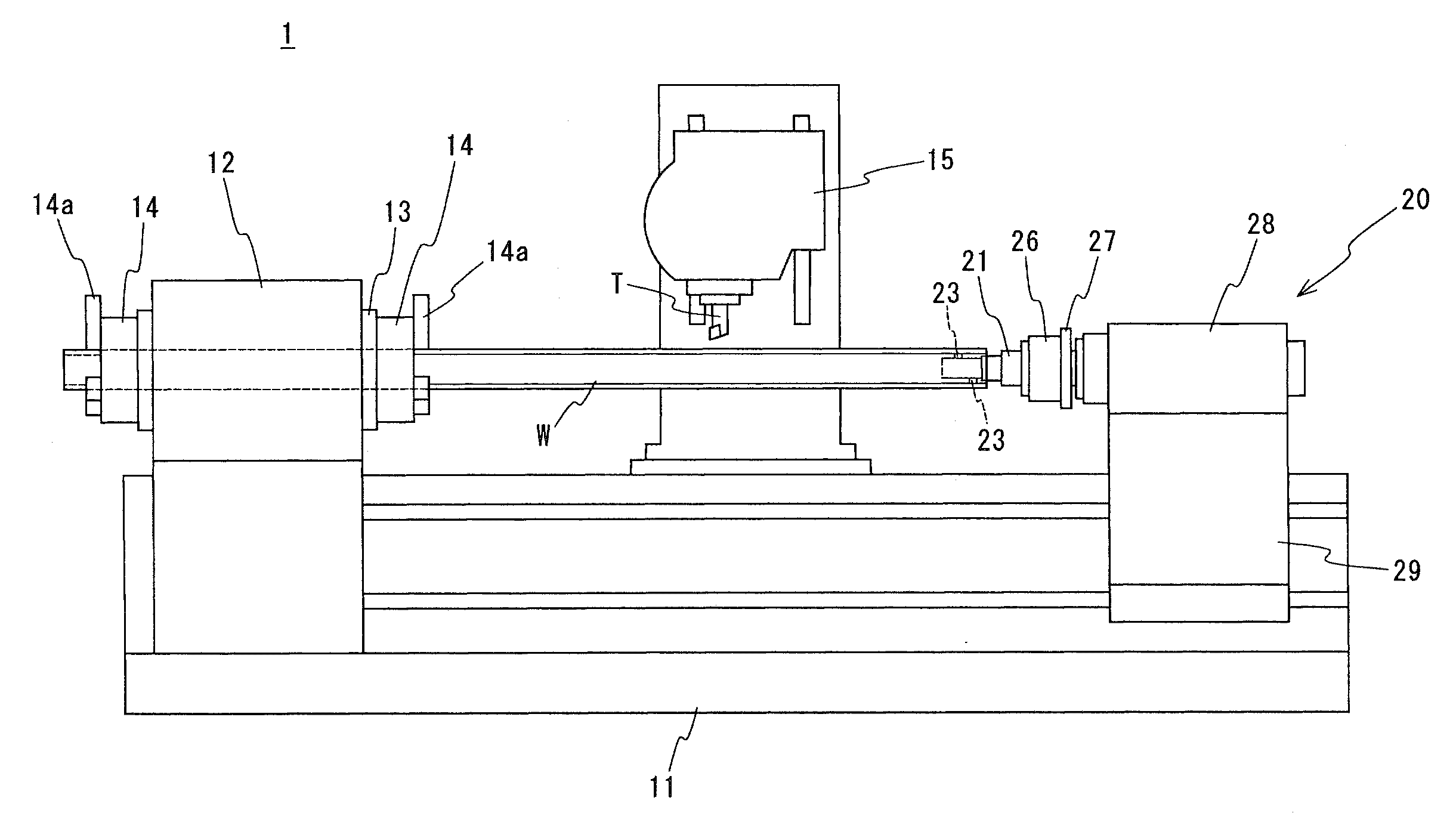
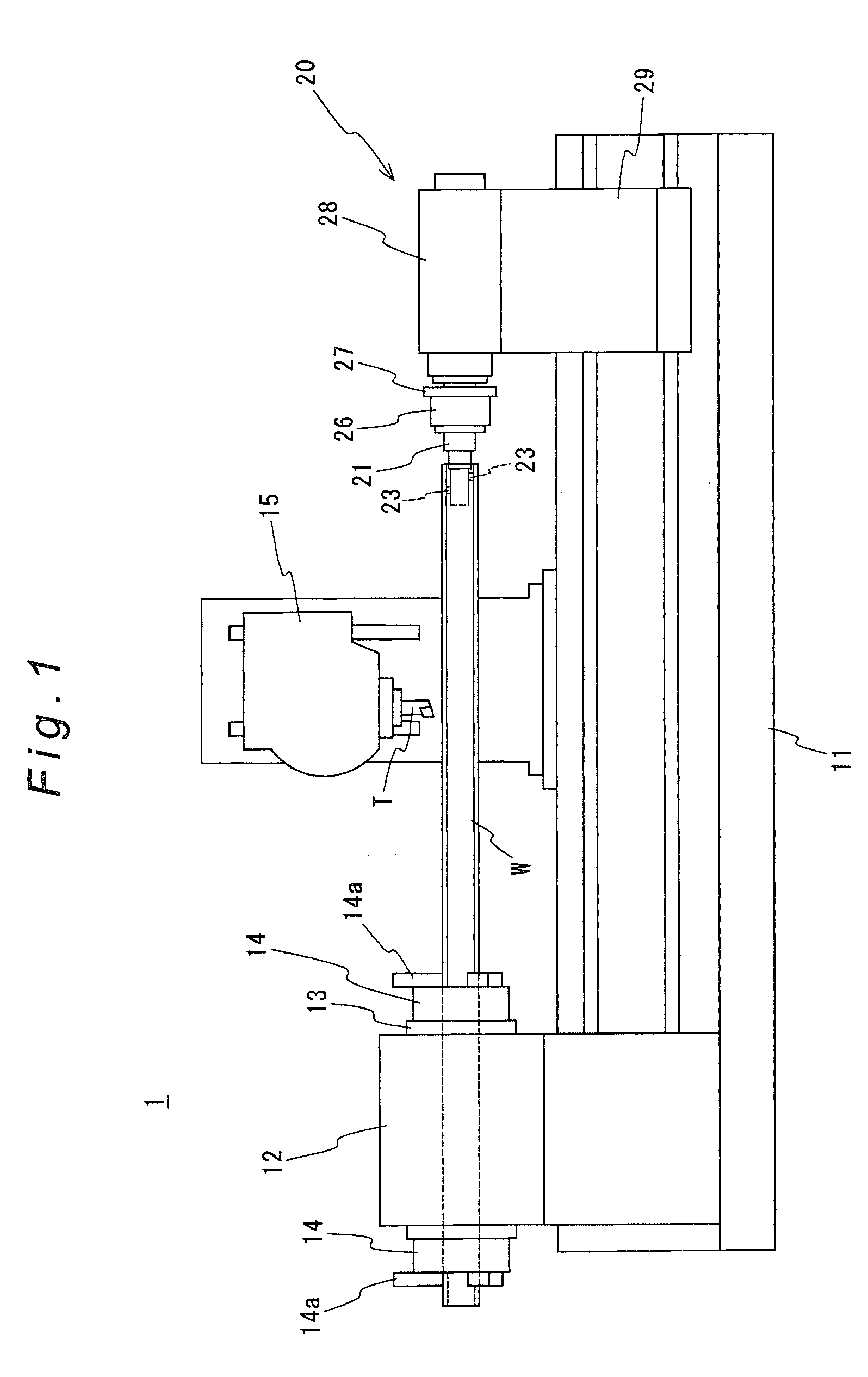
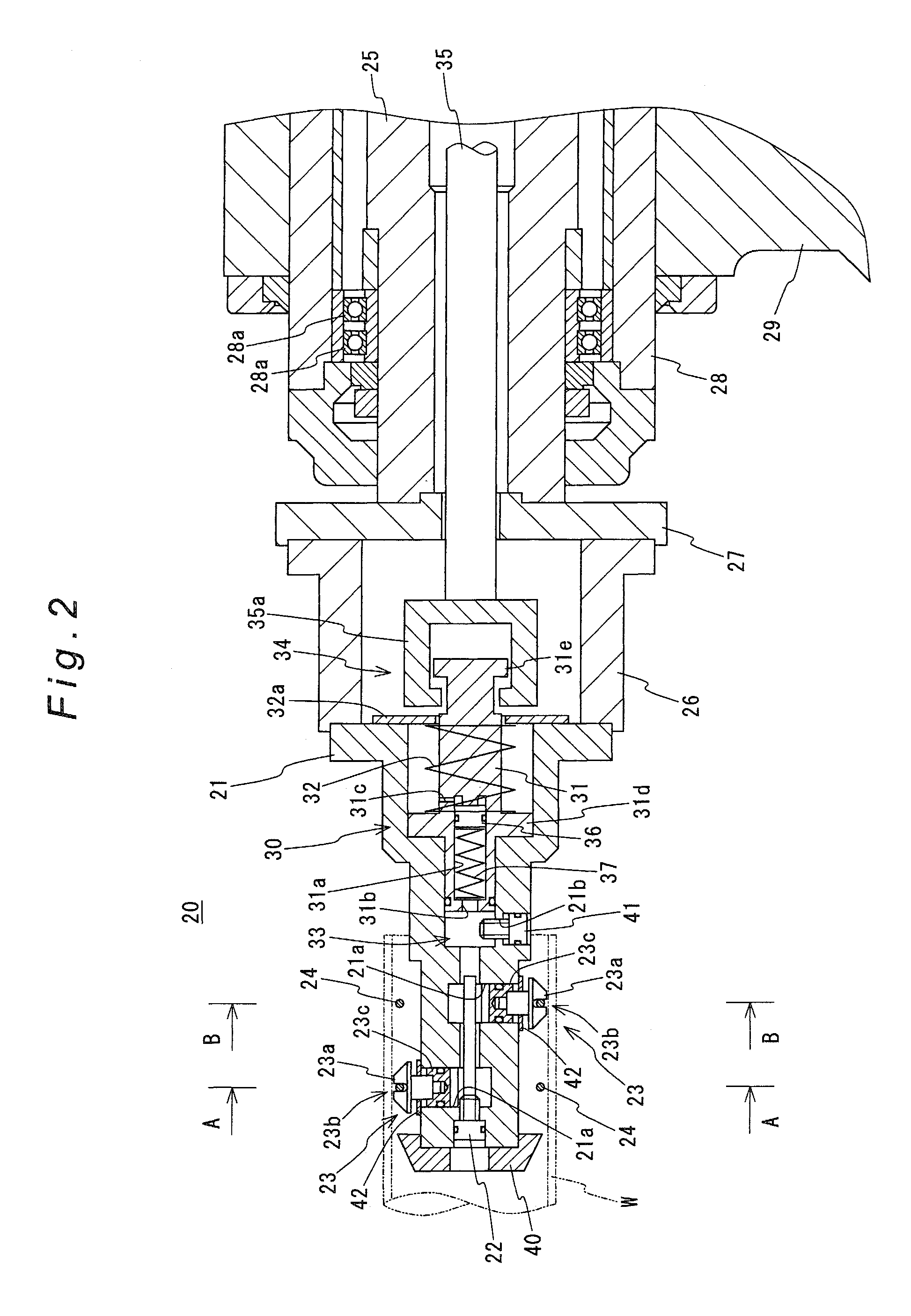
[0044]Hereinafter, a preferred embodiment of the present invention will be described with reference to the accompanying drawings. FIG. 1 is a front view showing a schematic configuration of a lathe according to one embodiment of the present invention. FIG. 2 is a cross-sectional view showing a schematic configuration of a holding mechanism according to the embodiment. FIG. 3 is a cross-sectional view as viewed in the arrow A-A direction in FIG. 2. FIG. 4 is a cross-sectional view as viewed in the arrow B-B direction in FIG. 2.

[0045]As shown from FIG. 1 to FIG. 4, a lathe 1 of the embodiment is configured to machine an outer circumferential surface of an annular workpiece W. The lathe 1 is provided with: a bed 11; a head stock 12 fixedly provided on the bed 11; a spindle 13, which is supported by the head stock 12 such that an axis line thereof is horizontal and in a manner to rotate freely around the axis line, for holding one end side of the workpiece W; a rotation drive mechanism ...


PUM


Abstract

The lathe comprises: a spindle for holding one end side of an annular workpiece W; a rotation drive mechanism for rotating the spindle; and a holding mechanism 20 for holding the other end side of the workpiece W. The holding mechanism 20 comprises: an inserting member 21 which is arranged to rotate freely and of which distal end is inserted into an interior of the other end side of the workpiece W; a support member 28 which supports the inserting member 21 to rotate freely; a plurality of contact members 23 which are arranged on an outer circumferential surface of the distal end of the inserting member 21 and which outwardly protrude to be in contact with an inner circumferential surface of the workpiece W; and a drive mechanism 30 for driving each of the contact members 23 so as to be brought into contact to each other.

Description

BACKGROUND OF THE INVENTION[0001]1. Technical Field[0002]The present invention relates to a lathe which comprises a spindle which is arranged to rotate freely around an axis line and which holds one end side of an annular workpiece; a rotation drive mechanism for rotating the spindle around the axis line; and a holding mechanism which is arranged to opposite to the spindle in a manner to be kept apart by an interval in an axial direction of the spindle and which holds the other end side of the workpiece, and which is configured to machine an outer circumferential surface of the workpiece.[0003]2. Description of the Related Art[0004]In a case of machining an outer circumferential surface of an annular and lengthy workpiece W, as shown in FIG. 11, it has been conventionally proposed machining by using a lathe disclosed in Japanese Unexamined Patent Application Publication No. 09-066401, for example.[0005]Similar to the general lathe, the lathe is comprised mainly of: a bed; a head sto...

Claims


Application Information

Patent Timeline
Patent Type & Authority Applications(United States)
IPC IPC(8): B23B23/00
CPCB23B23/025Y10T82/2564B23B31/40B23B31/16287
Inventor UEMURA, YOSHITANEKAWASAKI, KOJIYAMAMOTO, DAIGO
Owner DMG MORI CO LTD
Why Eureka
Try Eureka