Tamper-resistant electrical wiring device system

a technology of electrical wiring and tamper-resistant devices, which is applied in the direction of coupling device connections, electrical apparatus casings/cabinets/drawers, casings/cabinets/drawers details, etc., can solve the problems of electrical shock, disconnecting the circuit, and people may still experience an initial temporary shock

Active Publication Date: 2008-07-03
LEVITON MFG
View PDF89 Cites 32 Cited by
  • Summary
  • Abstract
  • Description
  • Claims
  • Application Information

AI Technical Summary

Benefits of technology

[0024]Advantages of this design include but are not limited to, a tamper-resistant electrical receptacle that is permanent in that once the unit is installed it offers protection for the life of the building structure. The tamper-resistant electrical receptacle in accordance with the present invention is reliable since this receptacle is not manually removable. In addition, a user need not be concerned about losing the associated part that makes the electrical receptacle tamper-resistant. Further, a user needs to be concerned with breaking the tamper-resistant electrical receptacle because the platform sub-assembly is secured behind the cover of the electrical receptacle. Moreover, the tamper-resistant electrical receptacle provides automatic protection even when a plug is removed because the spring loaded slider retracts back to the closed position for immediate protection.

Problems solved by technology

Since a large percentage of these receptacles are used in residential buildings and are located near the floor, a young child or infant, for example, may insert a small object into either one of the apertures which potentially may result in electrical shock.
More particularly, a burn or shock may result when a child's wet mouth enables electrical contact, wherein a path exists from the hot contact through the child to ground, establishing a ground fault.
Research studies have shown that many of these incidents happen around meal time, when parents are occupied in the kitchen and children are not well supervised.
The ground fault circuit interrupter, however, only disconnects the circuit after electrical contact is made with a conductor.
Thus, without a tamper resistant electrical receptacle, a person may still experience an initial temporary shock.
No such device, however, has achieved wide acceptance; therefore, the aforementioned condition remains today.
This is primarily due to ineffectiveness of each device, expense, and the lack of ease of use.
Foremost among these drawbacks is one of expense.
However, the added expense required to manufacture such receptacles outweighs the safety advantage.
These plastic receptacle caps, however, are unreliable and inefficient.
Other disadvantages of plastic receptacle caps include but are not limited to the forgetfulness of adults to reinsert the caps.
In addition, receptacles are susceptible to being exposed to a child who may pull a lamp cord, leaving the receptacle unprotected.
Furthermore, constant pressure from the plastic blades on the receptacle contacts increase contact distortion, increasing the risk of loose contacts and / or creating poor contacts, resulting in plugs falling out of the receptacle.
Moreover, many of the plastic receptacle caps may create choking hazards, since they may fail to pass a choke hazard test described in a UL standard.
However, none of the sliding shutter plates that are on the market are UL listed.
This is primarily due to the fact that they add extra layers of material between the plug prongs and the receptacle contacts which reduces the surface of contact between plug prongs and contacts, causing potential heat rise or arcing which may also be hazardous.
Another disadvantage of a manually movable face plate is that a small child, by observation, may learn to expose the electric receptacle.

Method used


Image

  • Tamper-resistant electrical wiring device system
  • Tamper-resistant electrical wiring device system
  • Tamper-resistant electrical wiring device system

Examples


first embodiment

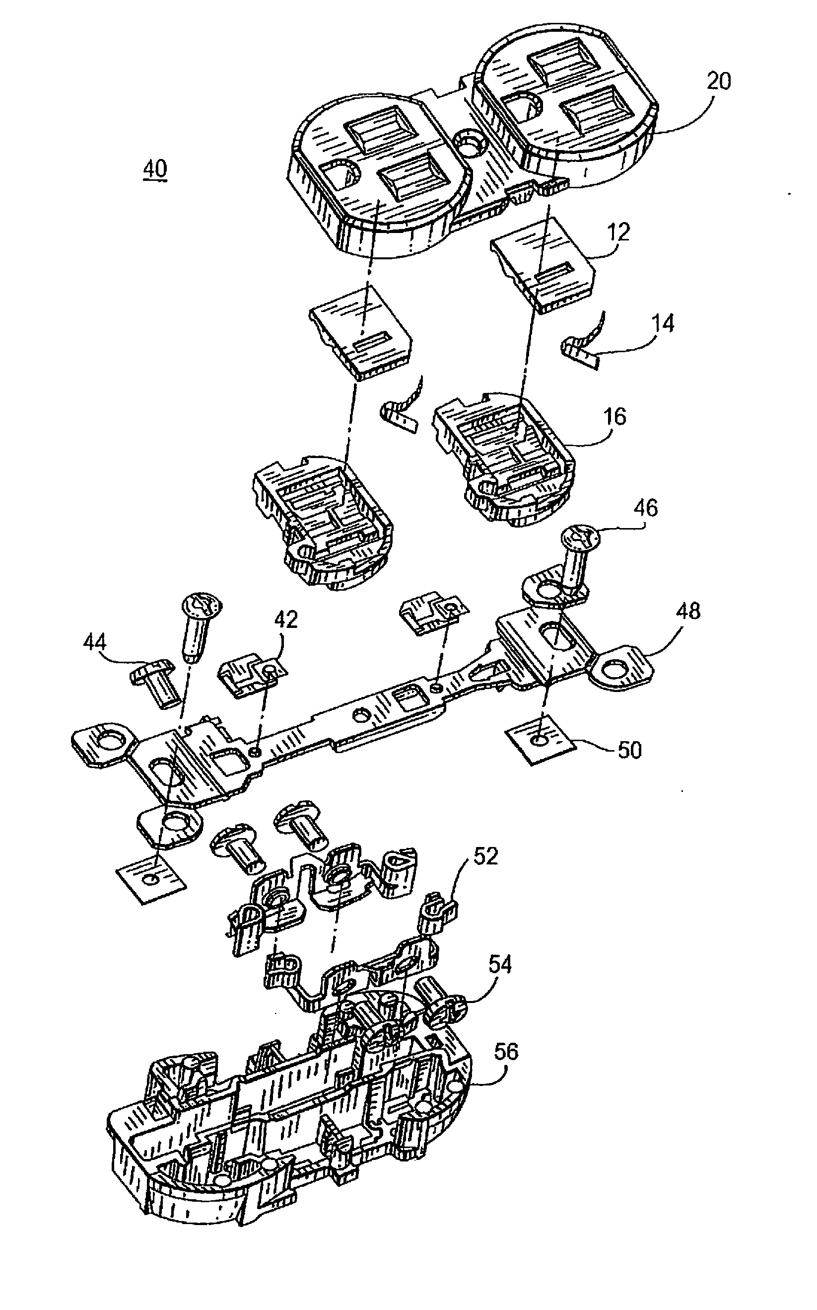
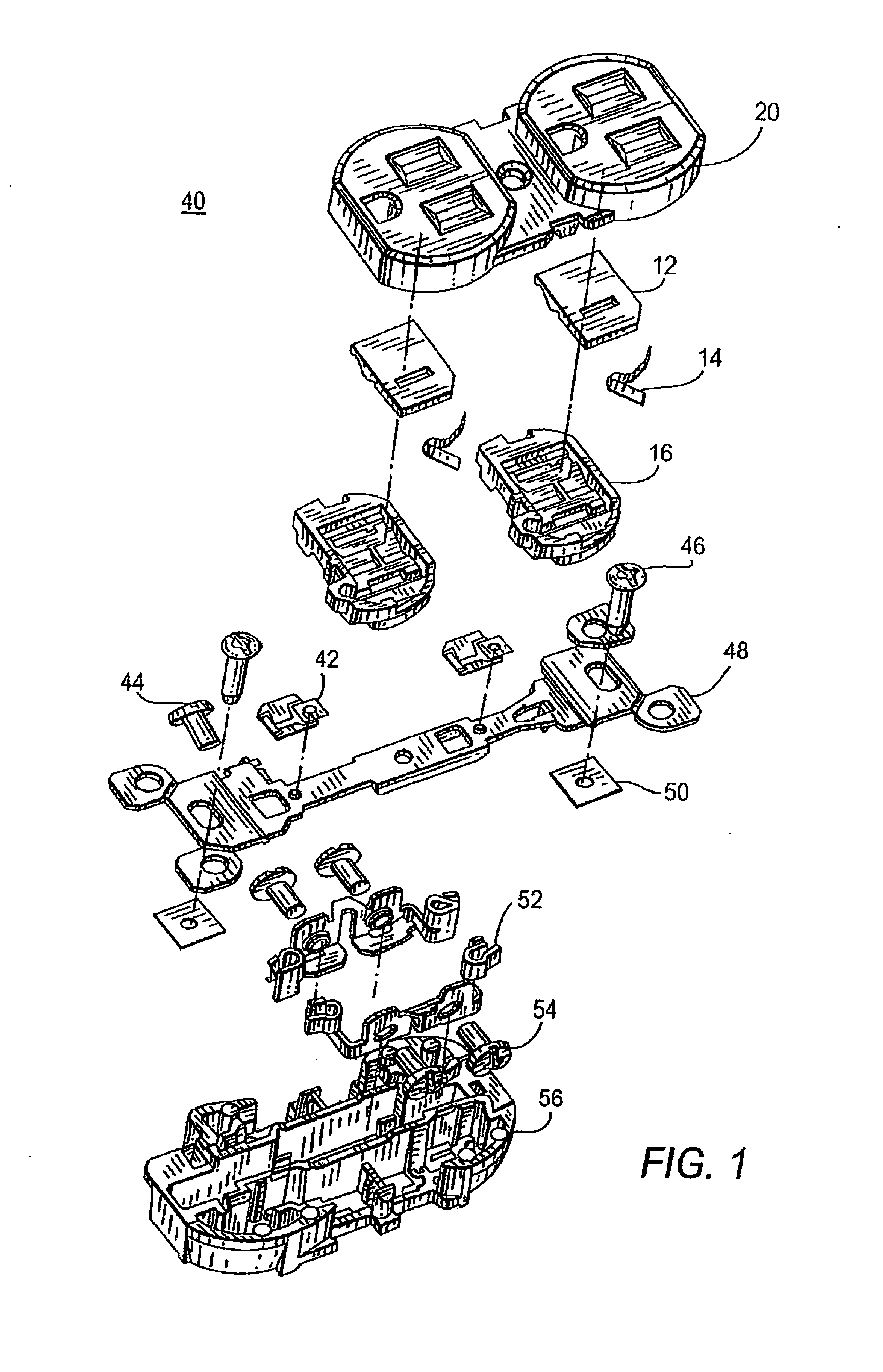
[0079]FIGS. 1-14b illustrate the tamper resistant receptacle 40 in accordance with the present invention. Specifically, FIG. 1 shows an exploded view of the tamper resistant electrical receptacle 40 in accordance with the present invention. The receptacle 40, as shown in FIG. 1, is a duplex three-prong electrical receptacle for handling 15 amp current applications. However, it should be understood that the receptacle can be a two or three-prong electrical receptacle or a receptacle other than that of a duplex receptacle.

[0080]As shown in FIG. 1, cover 20 sits on top of a pair of platform sub-assemblies including platform 16, leaf spring 14 and slider 12. Mounting screws 46 mount strap 48 onto the base 56 using retaining washers 50. Ground contacts 42 connect onto strap 48. Finally, contacts 52 connect to the base 56 using terminal screws 54 to form the receptacle terminals in base 56.

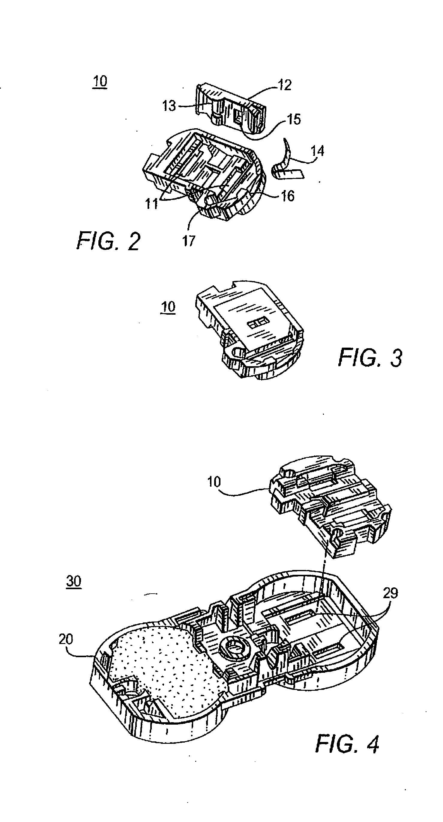
[0081]Specifically, referring to FIG. 2, an exploded view of the platform sub-assembly includes a sl...

second embodiment

[0091]FIGS. 15-27 depict the component assemblies for the tamper-resistant receptacle 300 in accordance with the present invention. The receptacle 300, as shown in FIG. 15, is a duplex three-prong electrical receptacle for handling 20 amp current applications. However, it should be understood that the receptacle can be a single two or three-prong electrical receptacle or a receptacle other than that of a duplex receptacle. In addition, the receptacle can have ground fault circuit interrupter (GFCI) capabilities. The receptacle also can be selected to handle other current capacities such as 30 amp, 50 amp, and other capacities.

[0092]FIG. 15 shows an exploded view of the 20 ampere embodiment of the tamper resistant electrical receptacle in accordance with the present invention. From the top of FIG. 15, cover 150 sits on top of platform sub-assembly 100 including platform 106, leaf spring 104 and slider 102. Terminal screws 256 connect the contacts 254 and wire nut 252 together within ...

embodiment 40

[0093]In particular, and focusing upon the platform sub-assembly 100, FIG. 16a illustrates an exploded view of the platform sub-assembly 100 which includes a slider 102, a leaf spring 104, and a platform 106. Slider 102 includes at least one rib 120 displayed in FIGS. 22a, 22b, 24a and 24b. Similar to the previously described embodiment 40, it is noted that rib 120 may be one or more than one projections (not shown). Slider 102 includes a slider aperture 110 for alignment with the aperture of cover 150 which is explained in detail hereinafter. Leaf spring 104 is mounted in the pocket 107 of platform 106 as is shown in the series of FIGS. 18a, 18b, 19a, 19b, 20a, and 20b. FIGS. 23a and 23b, front and back views of leaf spring 104.

[0094]Accordingly, leaf spring 104 rests in the pocket 107 of platform 106 to bias slider 102 in place in a first position where the slider aperture 110 is misaligned with either aperture 111 of the platform 106. Specifically, leaf spring 104 is driven into ...


PUM


Abstract

A tamper-resistant electrical receptacle includes a cover defining a set of cover apertures; and a slider defining an aperture therein and being movable between a first position blocking the set of cover apertures and a second position not blocking the set of cover apertures, wherein when an object probes at least one and fewer than all of the set of cover apertures, the slider is constrained in the first position. When a set of prongs is inserted simultaneously through the set of cover apertures, the prongs contact a slider surface that is oriented substantially orthogonal to a longitudinal axis of the set of prongs such that the slider is urged from the first to the second position. When in the second position the slider aperture aligns with at least one of the set of cover apertures to enable the set of prongs to contact the receptacle contacts.

Description

CROSS-REFERENCE TO RELATED APPLICATIONS[0001]The present application is a Continuation-in-Part application claiming the benefit of and priority to U.S. application Ser. No. 11 / 470,995, filed on Sep. 7, 2006, which in turn claims the benefit of and priority to U.S. Provisional Application Ser. No. 60 / 715,081, filed on Sep. 8, 2005, the entire content of each of which being incorporated herein by reference.FIELD OF THE INVENTION[0002]1. Technical Field[0003]The present invention relates to electrical receptacles, and, more particularly, to a tamper-resistant electrical wiring device system.[0004]2. Background of the Invention[0005]Electrical power transmitted from a source to a point of use through an electrical distribution system within a home or a commercial building for equipment and operations is a beneficial service. Conventional electrical receptacles within such a distribution system include a pair of slots or apertures aligned with contacts, wherein prongs of an electric plug...

Claims


Application Information

Patent Timeline
Patent Type & Authority Applications(United States)
IPC IPC(8): H01H9/02
CPCH01R13/4534H01R13/652H01R2103/00H01R25/006H01R24/78
Inventor CASTALDO, COSMOILKHANOV, AZER
Owner LEVITON MFG
Why Eureka
Try Eureka