Aperture coupled microstrip antenna

a microstrip antenna and antenna technology, applied in the direction of antennas, antenna details, basic electric elements, etc., can solve the problems of increased design difficulty, low bandwidth, and large product volum

Active Publication Date: 2008-07-03
DELTA ELECTRONICS INC
View PDF4 Cites 10 Cited by
  • Summary
  • Abstract
  • Description
  • Claims
  • Application Information

AI Technical Summary

Benefits of technology

[0025]According to the modulation method for a microstrip antenna couple with an aperture of the present invention, the microstrip antenna includes one metal ground plane, one feed line, and one radiant metal sheet, wherein the metal ground plane is formed on a first plane, the feed line is formed on a second plane paralleled to the first plane, the radiant metal sheet is formed on a third plane paralleled to the first plane, and the second plane and the third plane are arranged on different sides of the first plane. The modulation method includes the steps of: (a) performing a simulation of the microstrip antenna in a relatively higher order operation mode, in order to obtain a current distribution of the radiant metal sheet in the relatively higher order operation mode, (b) adjusting a location and a shape of the feed line, in order that a current distribution of the feed line and the current distribution of the radiant metal sheet in the same phase area have their respective maximum values, and (c) obtaining a matched impedance by adjusting the feed line, in order to excite the microstrip antenna operated in the relatively higher order operation mode and obtain an omnidirectional radiation pattern of the microstrip antenna.

Problems solved by technology

However, the drawbacks of the dipole antenna lies in that the dipole antenna is protruded from the product and the product volume and the difficulty of the design are increased.
The drawback of the microstrip antenna fed into the coaxial cable is the narrow bandwidth, and it is generally used in the mobile phone with the narrower bandwidth demand, such as GSM system.
However, the bandwidth is about 3% in the 2.4 GHz application, which is insufficient to provide enough bandwidth in the standard of 802.11b / g in the presently mainstreamed wireless network.
At the same time, it remains to be insufficient for the progressive wireless surroundings.

Method used


Image

  • Aperture coupled microstrip antenna
  • Aperture coupled microstrip antenna
  • Aperture coupled microstrip antenna

Examples


first embodiment

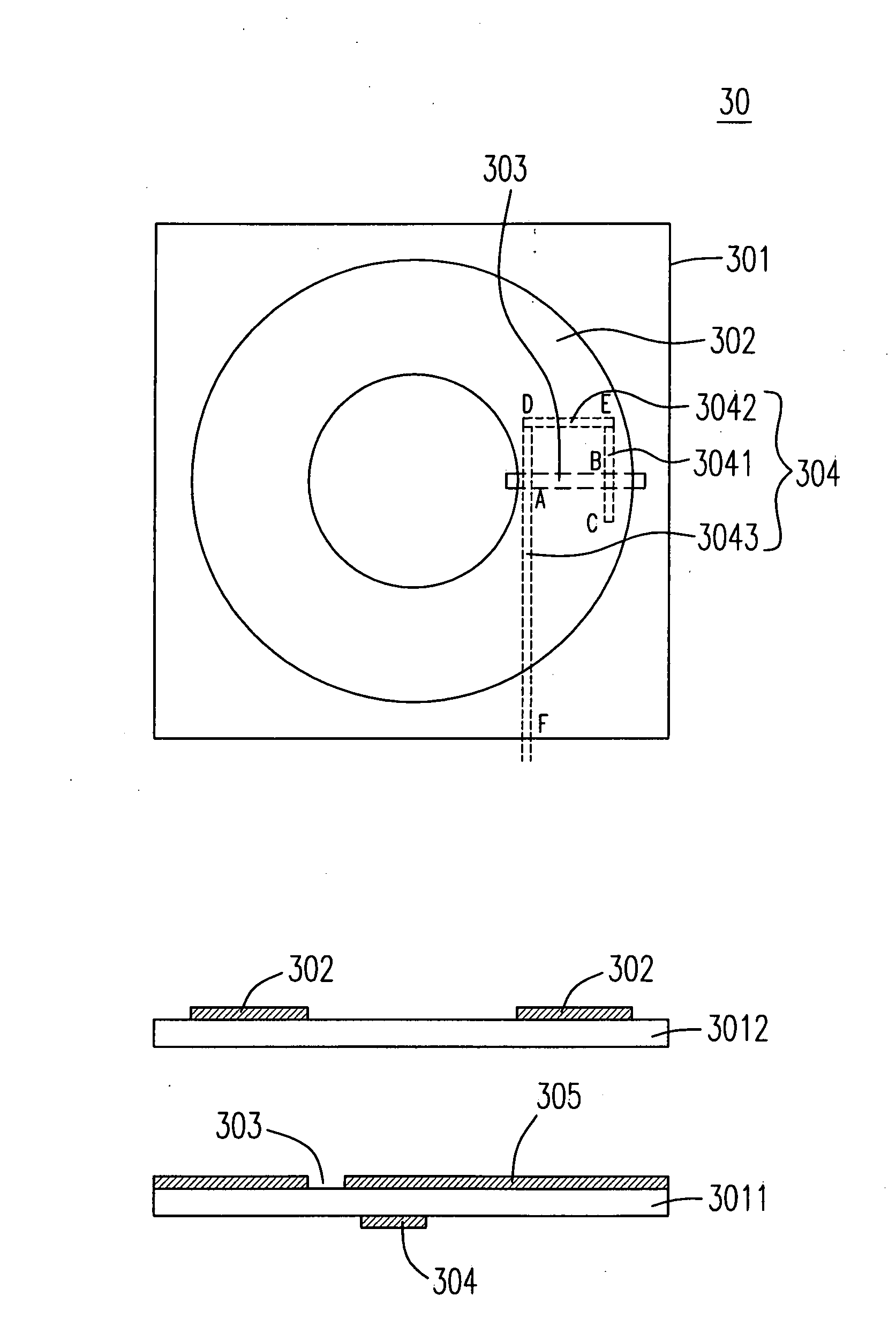
[0051]The difference between the microstrip antenna 40 and the microstrip antenna 30 of the first embodiment simply lies in that the arrangement of the feed line 404 is the mirror image of the feed line 304 on the horizontal projection plane. The feed line 404 arranged near to the inner edge and the outer edge of ring-shaped radiant metal sheet 402 is linear, including a first segment (L1) 4041 arranged near to the inner edge of the ring-shaped radiant metal sheet 402 and a second segment (L2) 4043 arranged near to the outer edge of the ring-shape radiant metal sheet 402, wherein the first segment (L1) 4041 passes through the intersection B and the endpoint C and the second segment (L2) 4043 passes through the intersection A and feeding point F.

second embodiment

[0052]When the length of the feed line 404 from the intersection A to the endpoint C is the length Ls, the current distribution of the ring-shaped radiant metal sheet 402 also matches successfully with that in the relatively higher order operation mode, the relatively higher order operation mode of the microstrip antenna 40 is excited successfully, and the omnidirectional radiation pattern of the microstrip antenna is obtained on the horizontal projection plane. Please refer to FIG. 9, wherein is the diagram showing the frequency and the return loss of the relatively higher order operation mode of the microstrip antenna in accordance with the present invention. It is recognized that the bandwidth of the microstrip antenna is about 200 MHz (9%), and the biggest antenna gain is also 5 dBi. Therefore, the obvious operation efficiency of the wireless network is achieved.

[0053]Please refer to FIG. 10, which is a structural diagram showing the microstrip antenna in accordance with the thi...


PUM


Abstract

An microstrip antenna is provided. A microstrip antenna includes a first substrate with a first surface and a second surface paralleled to each other, a metal ground plane with an aperture deposed on the first surface and exposed parts of the first substrate via the aperture and a metal feed line deposed on the second surface, the metal feed line has at least two intersections with the aperture on a horizontal projection plane, in order to feed a signal received or transmitted by the microstrip antenna.

Description

FIELD OF THE INVENTION[0001]The present invention relates to a microstrip antenna. In particular, the present invention relates to an aperture coupled microstrip antenna.BACKGROUND OF THE INVENTION[0002]One Antenna is a coupling element or a conductive system interchanging electromagnetic energy of the circuit. When transmitting the signal, the electricity of the radio frequency is transferred by the antenna to the electromagnetic energy and is radiated to the surroundings. When receiving the signal, the electromagnetic energy received by the antenna is transferred to the electricity of the radio frequency which is provided and accessed to the processor. Generally speaking, the characteristic and the efficiency of the antenna are obtained from the parameters, such as operation frequency, radiation pattern, return loss, and antenna gain, etc., wherein the radiation pattern resulting from the antenna radiate energy in all directions is the characteristic of the antenna radiation descr...

Claims


Application Information

Patent Timeline
Patent Type & Authority Applications(United States)
IPC IPC(8): H01Q1/38H01Q9/04
CPCH01Q9/0464H01Q9/0457
Inventor YU, MING-JULI, HSIN-CHUNG
Owner DELTA ELECTRONICS INC
Why Eureka
Try Eureka