Trigger system for data reading device

a data reader and trigger technology, applied in the field of trigger systems for data reading devices, can solve the problems of increasing the difficulty of troubleshooting of automated systems, increasing the complexity of the overall system wiring, and increasing the cost of installation of the system, so as to improve reliability and reduce cos

Active Publication Date: 2008-07-03
COGNEX CORP
View PDF5 Cites 19 Cited by
  • Summary
  • Abstract
  • Description
  • Claims
  • Application Information

AI Technical Summary

Benefits of technology

[0006]The present invention provides a method for triggering a data reader to acquire a high resolution, decodable image, by using the imaging system co

Problems solved by technology

These sensors are hard wired to the conveyors or elsewhere along the expected path of a moving object, and therefore add not only cost, but complexity to the wiring of the overall system.
These sensors, therefore, make installation of the system more

Method used


Image

  • Trigger system for data reading device
  • Trigger system for data reading device
  • Trigger system for data reading device

Examples


Embodiment Construction

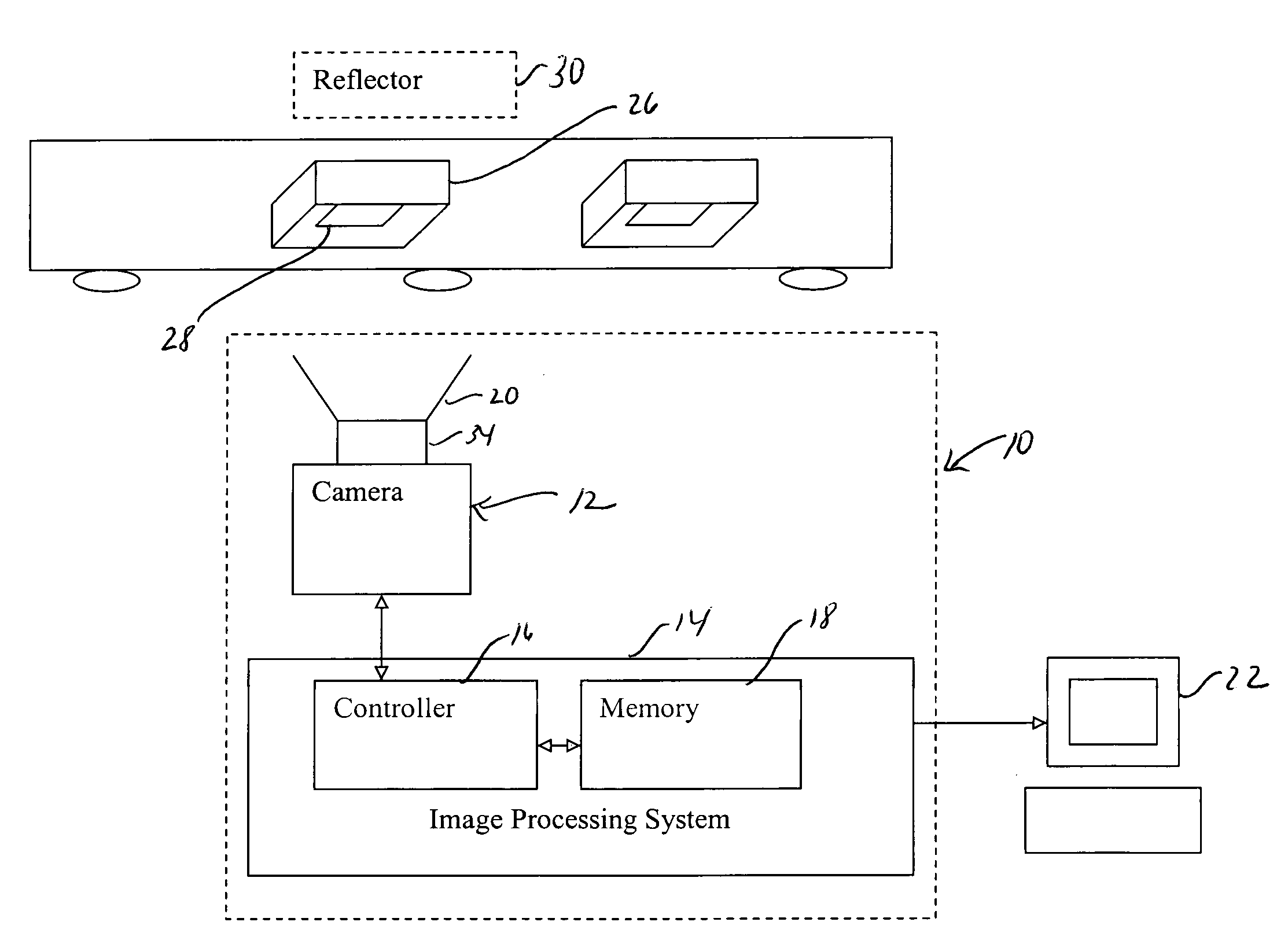
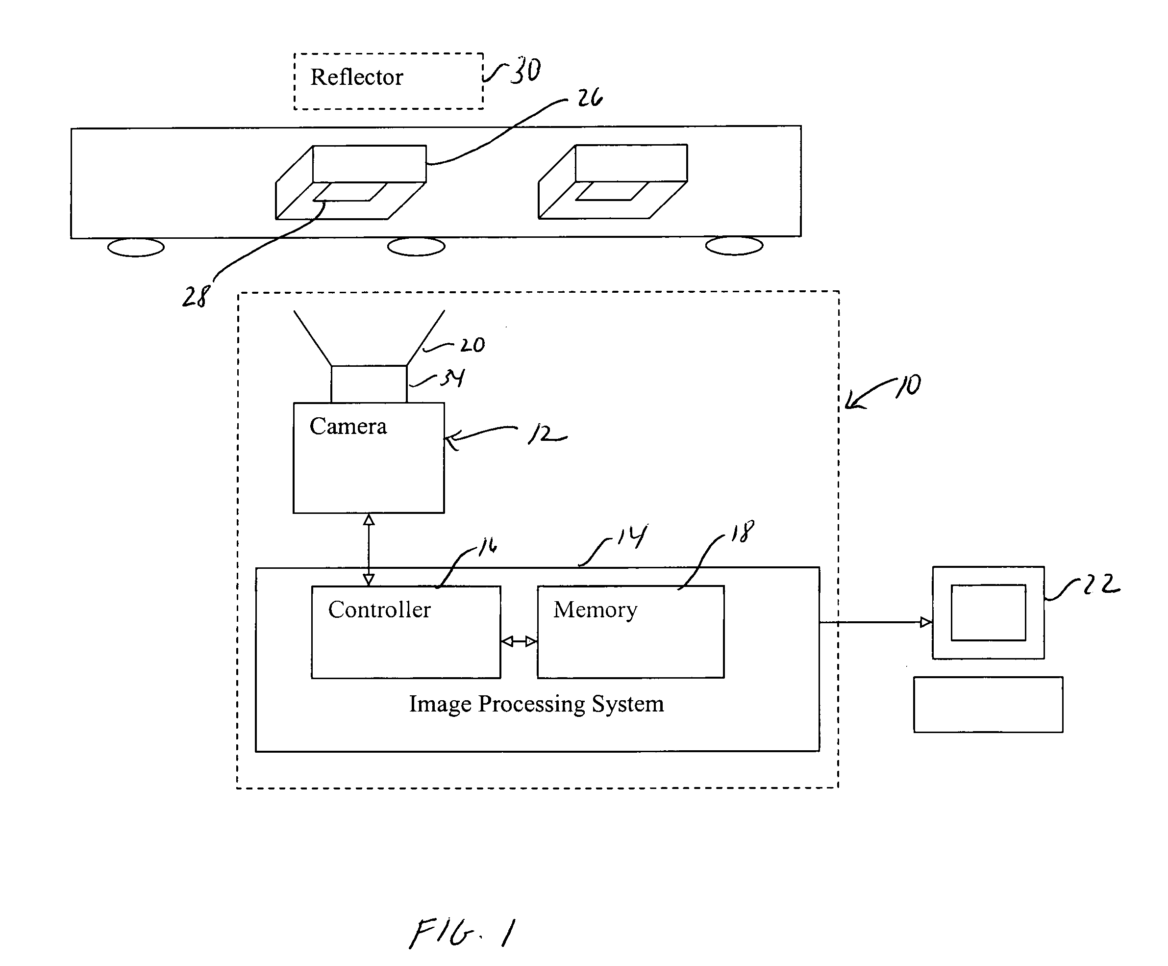
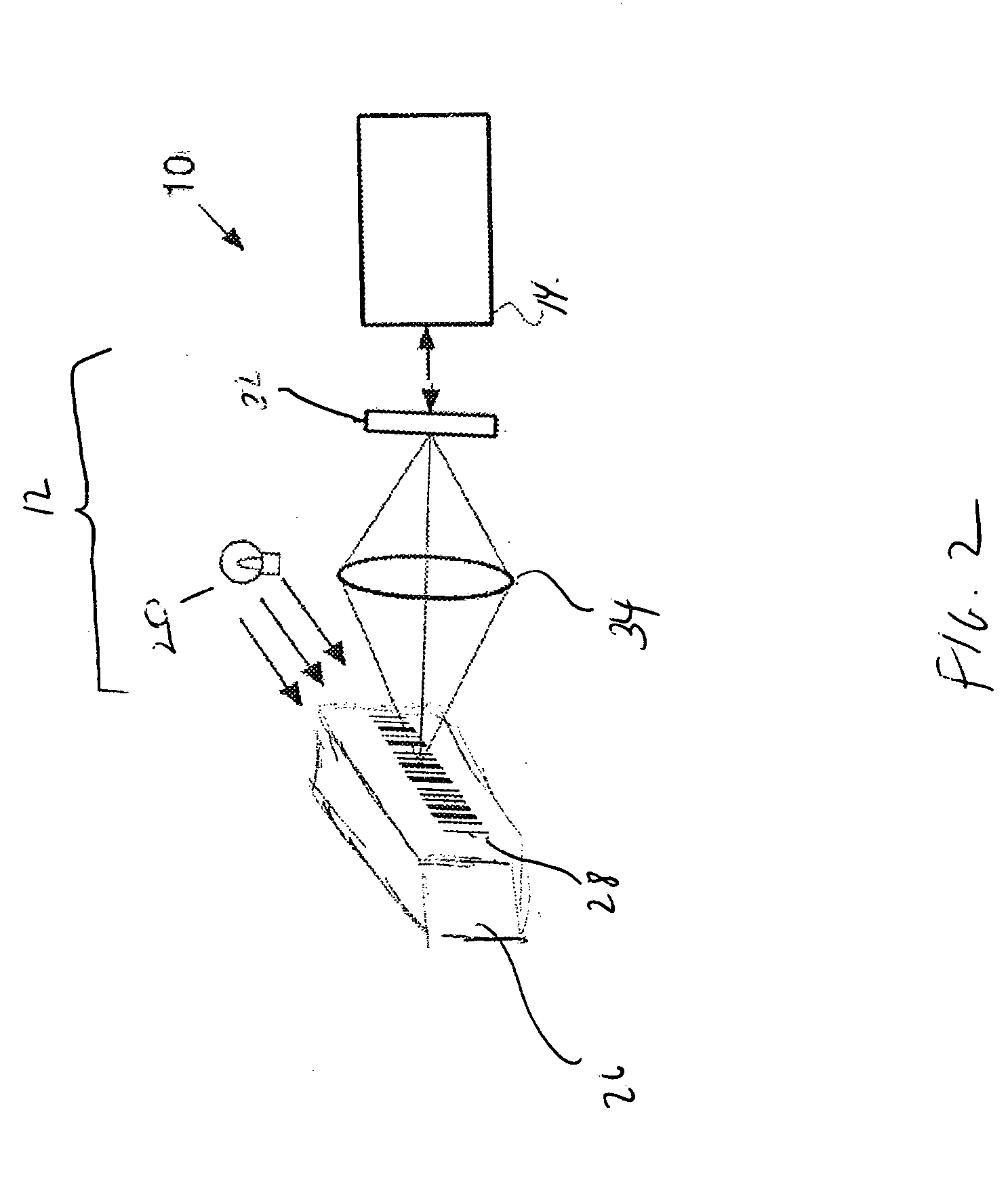
[0014]Referring now to the Figures and more particularly to FIG. 1, a data reader 10 constructed in accordance with the present invention is shown. The data reader 10 comprises a camera 12 which can include an optical system 34 and one or more light source 20. The camera 12 is coupled to an image processing system 14 that includes a controller 16 and a memory element 18. The image processing system 14 includes a frame grabber for creating a series of fixed images from the image stream generated by the camera 12, and a vision application for decoding or otherwise processing the images acquired by the camera 12, and may be connected to an operator terminal 22. In operation, the controller 16 adjusts the resolution of the camera 12 to acquire low resolution image data until an object is detected, and triggers a high resolution image acquisition mode only when an object is detected, as described more fully below.

[0015]Referring still to FIG. 1, the camera 12 is positioned adjacent a con...


PUM


Abstract

A data reader comprises a camera that has an adjustable resolution and acquisition speed. The camera is maintained at a low level resolution and fast speed and is periodically actuated to acquire images. When an acquired image indicates that an object is present, the resolution of the camera is increased, and a higher resolution image is acquired and decoded. The imaging system of the camera is therefore used to trigger data acquisitions, thereby eliminating the need for external triggers and sensor devices.

Description

CROSS-REFERENCE TO RELATED APPLICATION[0001]Not applicable.STATEMENT CONCERNING FEDERALLY SPONSORED RESEARCH OR DEVELOPMENT[0002]Not applicable.FIELD OF THE INVENTION[0003]The present invention relates to methods and devices for triggering image data acquisition in a data reader.BACKGROUND OF THE INVENTION[0004]During mass production, packaging, shipping and other manufacturing, warehousing and retail processes, automated motion devices, including, for example, automated guided vehicles and conveyor belts, are used extensively to transport both component parts, manufactured components, completed products and packages between stations. To track the movement of these components, the parts on the conveyor belt or automated motion device are often marked with identifying symbols such as bar codes, data matrixes, symbols, identifying characters or other types of identifying data. This data is imaged by machine vision systems or other data reading devices that include a camera for acquiri...

Claims


Application Information

Patent Timeline
IPC IPC(8): H04N5/225G06V10/10
CPCG06K9/20H04N5/345H04N3/1562G06V10/10H04N25/44H04N25/42H04N25/447
Inventor REUTER, RICHARD
Owner COGNEX CORP
Why Eureka
Try Eureka