Eureka AIR delivers breakthrough ideas for toughest innovation challenges, trusted by R&D personnel around the world.

Thin-film magnetic head

a thin-film magnetic head and magnetic head technology, applied in the field can solve problems such as fluctuation of thin-film magnetic heads, and achieve the effects of reducing cracks, improving coating ratio, and keeping performances from fluctuating

Inactive Publication Date: 2008-07-03
TDK CORPARATION
View PDF12 Cites 0 Cited by
  • Summary
  • Abstract
  • Description
  • Claims
  • Application Information

AI Technical Summary

Benefits of technology

[0007]Meanwhile, manufacturing a thin-film magnetic head requires the steps of forming an organic insulating material such that the organic insulating material is interposed between turns adjacent to each other in a lead constituting a thin-film coil, and then slightly milling the whole surface of a substrate (wafer) so as to clean the wafer surface in order to improve the adhesion to an inorganic insulating material such as Al2O3 which will be formed later. If the lead constituting the thin-film coil is exposed at the upper face in the laminating direction here, the lead will be slightly milled, so as to reduce its cross-sectional area, thereby increasing the resistance value of the thin-film coil, while fluctuating the inductance of the thin-film coil.
[0009]It is therefore an object of the present invention to provide a thin-film magnetic head which can keep performances from fluctuating, while restraining an organic insulating material from peeling off.
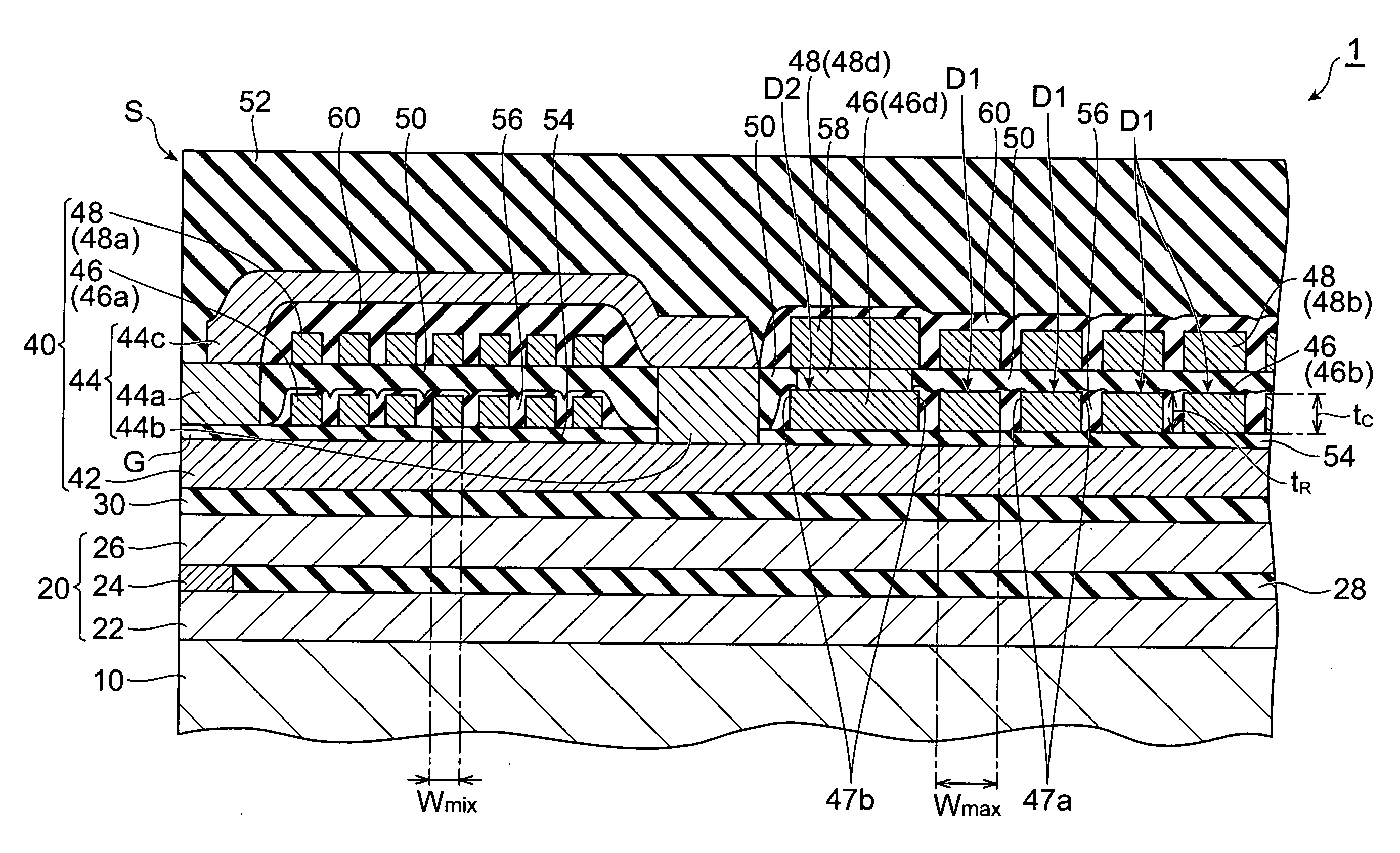
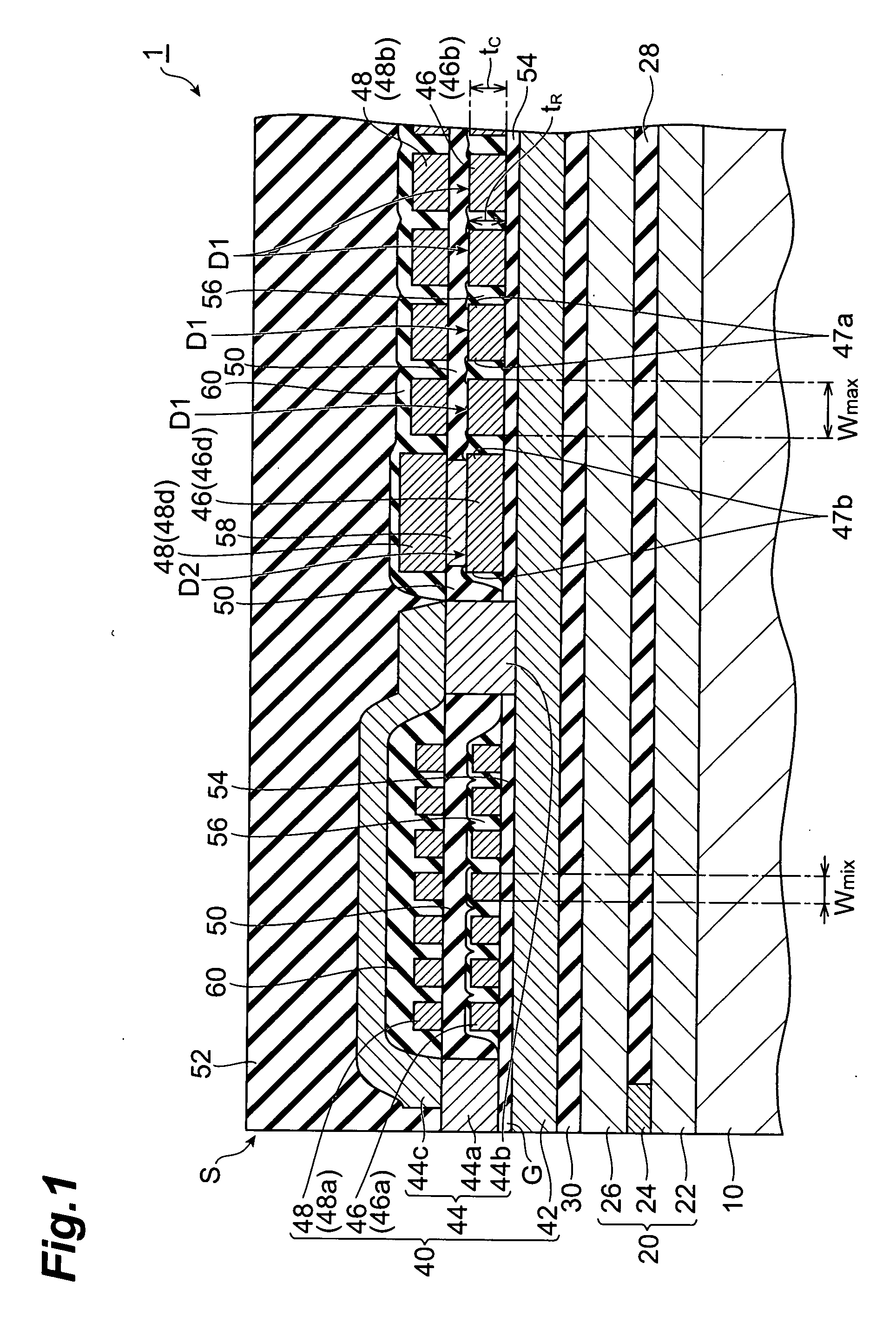
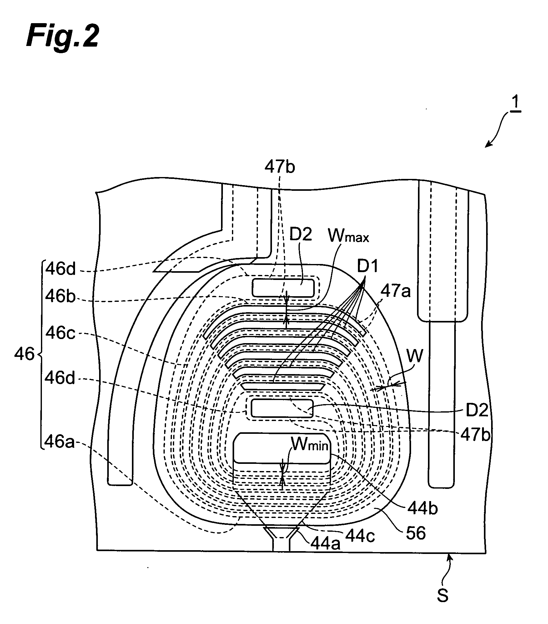
[0011]In the thin-film magnetic head in accordance with the present invention, an uncoated area which is free of the organic insulating material but covered with an inorganic insulating material, for example, is formed on the upper face of the maximum width part of the lead in the laminating direction. Therefore, no organic insulating material peels off under a thermal load and the like at the part formed with the uncoated area, whereby the peeling of the organic insulating material is suppressed as compared with the case where the whole upper face in the laminating direction of the lead is covered with the organic insulating material. In the thin-film magnetic head in accordance with the present invention, the upper face of the minimum width part of the lead in the laminating direction is totally covered with the organic insulating material. Therefore, the minimum width part of the lead is kept from being slightly milled at the time of cleaning the wafer surface, whereby the influence on characteristics of the thin-film coil is very small. As a result, performances of the thin-film magnetic head can be kept from fluctuating, while restraining the inorganic insulating material from peeling off. The width of the lead constituting the thin-film coil as seen from the upper side in the laminating direction (as seen from the laminated layer surface of the lead constituting the thin-film coil) corresponds to the distance from one edge to the other edge in a direction perpendicular to a tangent of a virtual line passing the center of the lead.
[0022]Preferably, the uncoated area is free of an edge part of the lead on the upper face side in the laminating direction, while the organic insulating material is formed so as to extend to the edge part. This can improve the coating ratio on the upper face of the lead in the laminating direction when forming the inorganic insulating material, and thus can reduce the occurrence of cracks in the vicinity of interfaces between the lead, the organic insulating material and the inorganic insulating material.
[0023]The present invention can provide a thin-film magnetic head which can keep performances from fluctuating, while restraining an organic insulating material from peeling off.

Problems solved by technology

This affects characteristics of the thin-film coil very much, which is problematic in that performances of thin-film magnetic heads fluctuate among products.

Method used


Image

  • Thin-film magnetic head
  • Thin-film magnetic head
  • Thin-film magnetic head

Examples


example 1

[0084]The present invention will now be explained more specifically with reference to Examples 1-1 to 1-9 and Comparative Examples 1-1 and 1-2 and FIG. 11, but is not restricted to the following examples. FIG. 11 is a table showing embodied conditions and evaluation results of Examples 1-1 to 1-9 and Comparative Examples 1-1 and 1-2.

example 1-1

[0085]On a substrate made of Al2O3.TiC, Al2O3 was laminated as an undercoat layer, so as to form the support 10. Then, according to the above-mentioned method of manufacturing the thin-film magnetic head 1, the reading head part 20, the insulating layer 30, the recording head part 40, the resist films 56, 60, and the insulating layers 50, 52 were formed, so as to yield the thin-film magnetic head 1. In the thin-film magnetic head 1 of Example 1-1, the lead width Wmin of the minimum width part 46a as seen from the upper part in the laminating direction was set to 1.9 μm, while the lead width Wmax of the maximum width part 46b as seen from the upper part in the laminating direction was set to 5.0 μm. Also, in the thin-film magnetic head 1 of Example 1-1, the thickness tC of the maximum width part 46b in the laminating direction was set to 2.0 μm, while the thickness tR of the resist film 56 in the laminating direction was set to 2.5 μm, so that the ratio tC / tR of the thickness tC of t...

examples 1-2 to 1-9

[0087]The thin-film magnetic heads 1 of Examples 1-2 to 1-9 were obtained as in Example 1-1 except that X was set to 0.2, 0.3, 0.4, 0.5, 0.6, 0.7, 0.8, and 0.9, respectively.


PUM


Abstract

A thin-film magnetic head which can keep performances from fluctuating, while restraining an organic insulating material from peeling off is provided.The thin-film magnetic head comprises a lower magnetic pole layer, an upper magnetic pole layer and a first thin-film coil. A resist film made of an organic insulating material is interposed between turns adjacent to each other in the lead constituting the first thin-film coil. The first thin-film coil has a minimum width part and a maximum width part. The minimum width part is arranged closer to an air bearing surface than is a second upper magnetic pole part, while the whole upper face of the minimum width part is covered with the resist film. The maximum width part is arranged on the side farther from the air bearing surface than is the second upper magnetic pole part, while the upper face of the maximum width part is formed with a resist-uncoated area free of the resist film.

Description

BACKGROUND OF THE INVENTION[0001]1. Field of the Invention[0002]The present invention relates to a thin-film magnetic head.[0003]2. Related Background Art[0004]A thin-film magnetic head in which the whole upper face of a lead constituting a thin-film coil is covered with an organic insulating material has conventionally been known (see, for example, Japanese Patent Application Laid-Open No. 2000-268321).[0005]Also, a thin-film magnetic head in which an organic insulating material is interposed between turns adjacent to each other in a lead constituting a thin-film coil, while an inorganic insulating material is in contact with the upper and lower faces of the lead in the laminating direction has conventionally been known (see, for example, Japanese Patent Application Laid-Open No. 2004-134039).SUMMARY OF THE INVENTION[0006]A thermal load or the like in a later step generates a stress in the organic insulating material, whereas the magnitude of the stress is in proportion to the volu...

Claims


Application Information

Patent Timeline
IPC IPC(8): G11B5/33
CPCG11B5/3123
Inventor HIRAKI, TETSUYAGOMI, HIROTAKAMAEJIMA, KAZUHIKO
Owner TDK CORPARATION
Why Eureka
Eureka Blog
Learn More