Electronic apparatus

a technology of electronic equipment and electronic components, applied in the field of electronic equipment, can solve problems such as user discomfort, achieve the effects of reducing the size of the electronic equipment, reducing the thermal resistance, and achieving the effect of heat radiation more efficiently

Inactive Publication Date: 2008-07-03
FUJITSU LTD
View PDF7 Cites 66 Cited by
  • Summary
  • Abstract
  • Description
  • Claims
  • Application Information

AI Technical Summary

Benefits of technology

[0018]The support stage may have elasticity and bring the heat-radiating plate into press contact with the heat-generating element by elastic force. This can reduce the thermal resistance between the heat-generating element and the heat-radiating plate and achieve the heat radiation more efficiently.
[0019]A portion of the heat-radiating plate that is in contact with the heat-generating element may be protruded toward the heat-generating element from the remaining portion of the heat-radiating plate. This can dispose another electronic component different from the heat-generating element between the heat-radiating plate and the substrate on which the heat-generating element is mounted and is effective in reducing the size of the electronic apparatus. The heat-radiating plate may have elasticity and bring the protruded portion into press contact with the heat-generating element by elastic force. This...

Problems solved by technology

However, it is necessary to prevent such a situation that the heat radiated from the heat-radiating plate increases the temperature of a housing of an electro...

Method used


Image

  • Electronic apparatus
  • Electronic apparatus
  • Electronic apparatus

Examples


embodiment 1

[0046]FIG. 12 schematically shows the configuration of a portable electronic apparatus (electronic apparatus) which is Embodiment 1 of the present invention. A portable electronic apparatus 100 of Embodiment 1 has a first body portion 30 and a second body portion 40 which is attached to the first body portion 30 to pivotally open or close about a hinge portion 42.

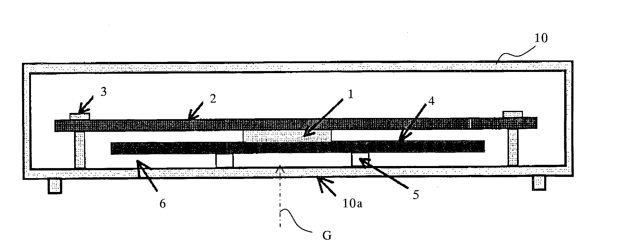
[0047]The first body portion 30 is formed to accommodate a heat-generating element 1, a substrate 2, and a heat-radiating plate 4 in a housing 10 which is a case made of resin such as plastic. A battery 16 is removably put in the housing 10. In the first body portion 30, an operation portion 12 having a keypad and other operation members disposed therein is provided on a housing front-wall 10a which is a front wall portion of the housing 10, that is, a first wall portion. The housing front-wall 10a is not necessary a wall with no opening, and in reality, has a plurality of openings for exposing the operation members.

[0048]I...

embodiment 2

[0078]FIG. 5 shows the configuration within a housing 10 forming a first body portion of a portable electronic apparatus which is Embodiment 2 of the present invention. In Embodiment 2, components identical to those in Embodiment 1 are designated with the same reference numerals as those in Embodiment 1 to substitute for description.

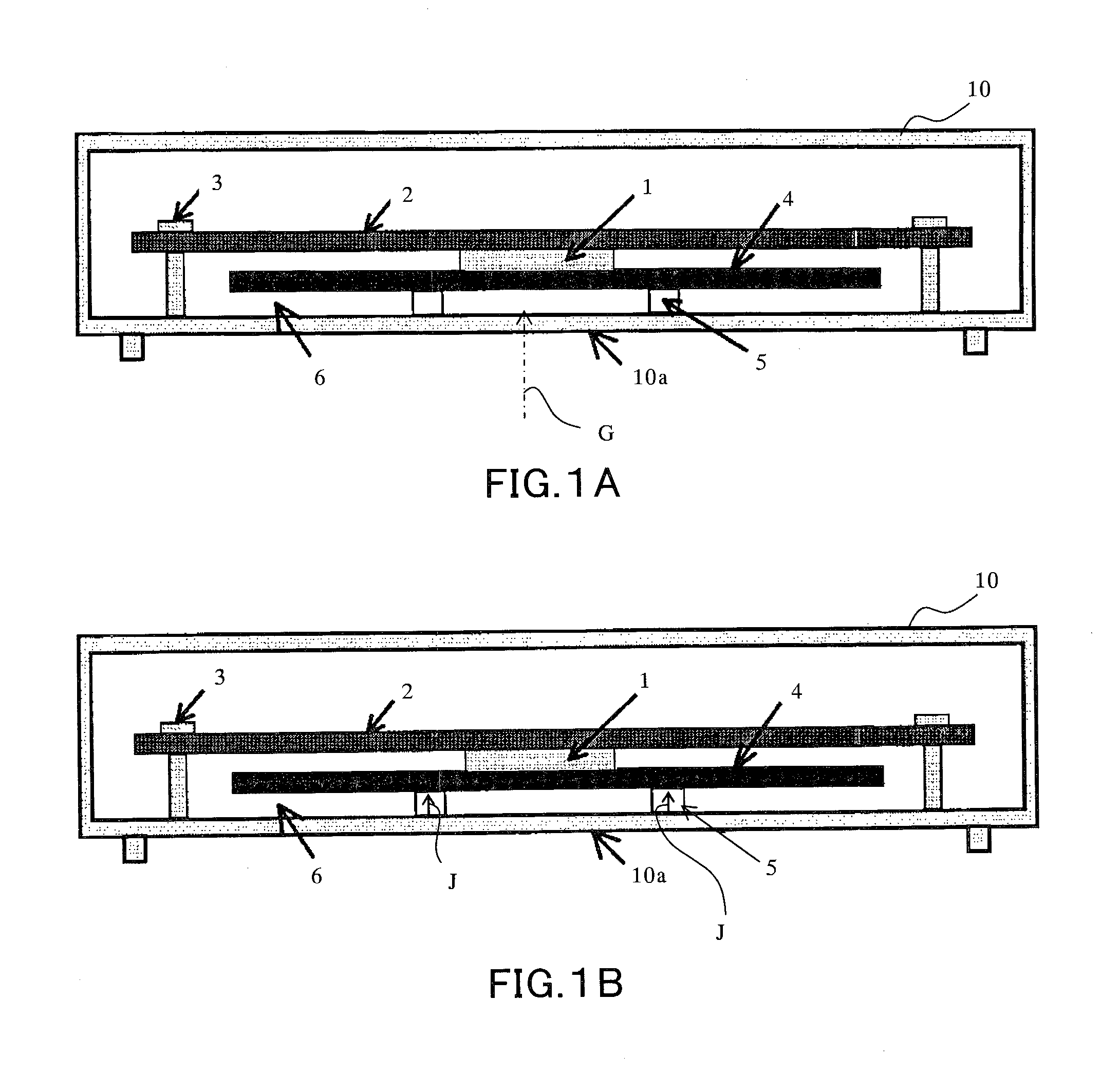
[0079]Embodiment 2 employs a shape in which a portion 4a′ of a heat-radiating plate 4′ that overlies a heat-generating element 1 is protruded from a peripheral portion (remaining portion) 4b′ toward a substrate 2. Specifically, the portion of the heat-radiating plate 4′ that is in contact with the heat-generating element 1 has a convex shape and the opposite side thereof has a concave shape.

[0080]When the heat-radiating plate 4′ is made of a material having elasticity, the heat-radiating plate 4′ is formed in such a shape to allow enhanced adhesion between the protruded portion 4a′ and the heat-generating element 1 by elastic force K produced in the heat...

embodiment 3

[0082]FIG. 6 shows the configuration within a housing 10 forming a first body portion of a portable electronic apparatus which is Embodiment 3 of the present invention. In Embodiment 3, components identical to those in Embodiment 1 are designated with the same reference numerals as those in Embodiment 1 to substitute for description.

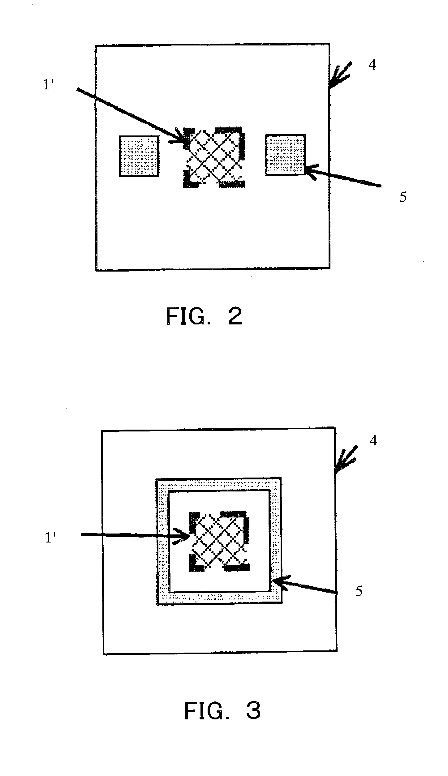
[0083]Embodiment 3 includes a heat-insulating member (heat-insulating plate) 7 of a plate shape having substantially the same size as that of a heat-radiating plate 4 in an in-plate direction such that the heat-insulating member 7 is in contact with a surface of the heat-radiating plate 4 closer to a housing front-wall 10a, and support stages 5 are placed between the heat-insulating member 7 and the housing front-wall 10a to provide an air layer 6. In other words, in Embodiment 3, the support stages 5 (air layer 6), the heat-insulating member 7, the heat-radiating plate 4, a heat-generating element 1, and a substrate 2 are arranged in the housing 10 in t...


PUM


Abstract

An electronic apparatus 100 includes a heat-generating element 1, a heat-radiating plate 4 which is used in heat radiation of the heat-generating element, and a housing 10 which accommodates the heat-generating element and the heat-radiating plate. The heat-radiating plate is disposed between the heat-generating element and a first wall portion 10a of the housing, and a support stage 5 for forming an air layer is disposed between the heat-radiating plate and the first wall portion. Since the heat-insulating effect of the air layer prevents the heat diffused from the heat-radiating plate from being easily conducted to the first wall portion, the formation of a heat spot in the first wall portion can be avoided even when the heat-generating element which generates a large amount of heat is used.

Description

[0001]This application is a continuation of PCT International No. PCT / JP2005 / 016314, filed on 6 Sep. 2005, which is hereby incorporated by reference herein in its entirety as if fully set forth herein.BACKGROUND OF THE INVENTION[0002]The present invention relates to an electronic apparatus which includes a heat-generating element such as an LSI in a housing.[0003]Electronic apparatuses such as laptop computers and cellular phones have been increasingly reduced in thickness and size, while there is a growing tendency for those apparatuses to generate more heat from electronic components such as LSIs included therein. For such heat-generating components, a cooling method has conventionally been employed which uses a heat sink (heat-radiating plate), a cooling fan or the like.[0004]A heat-radiating plate is formed of a material with high thermal conductivity and diffuses heat from a heat-generating component to perform heat radiation. However, it is necessary to prevent such a situatio...

Claims


Application Information

Patent Timeline
IPC IPC(8): H05K7/20F28D15/00
CPCG06F1/203H05K7/20445H04M1/0202
Inventor TSUNODA, YOSUKESUZUKI, MASUMIAOKI, MICHIMASA
Owner FUJITSU LTD
Why Eureka
Try Eureka