Optical fiber and the manufacturing method thereof

a manufacturing method and technology of optical fiber, applied in the direction of fibre light guides, lighting and heating apparatus, instruments, etc., can solve the problems of light emitting panel, relatively high manufacturing cost, and unsatisfactory light emitting uniformity, so as to reduce the risk of optical fiber snapping/deformation

Inactive Publication Date: 2008-07-03
IND TECH RES INST
View PDF7 Cites 62 Cited by
  • Summary
  • Abstract
  • Description
  • Claims
  • Application Information

AI Technical Summary

Benefits of technology

[0013]In view of the disadvantages of prior art, the primary object of the present invention is to provide an optical fiber having a plurality of microstructures formed upon a core of the aforesaid optical fiber, by which not only the plural microstructures are prevented from being damaged by normal usage and contacting to adhesive directly, but also they can lower the risk of the optical fiber being snapped / deformed while the optical fiber is subjecting to an external force and bended.

Problems solved by technology

However, although the weaving / platting operation is not necessary causing breakages to the optical fiber 5, the bending of each optical fiber 5 by the weaving / platting operation can not be controlled at will so that light emitting uniformity is not satisfactory, not to mention that its manufacturing cost is relatively higher as its structure is more complicated.
Furthermore, the light emitting panel, by its very nature, is only marginally flexible since the woven plait of the optical fibers 5 may be deformed and thus change the bending degree of each sharp bend when the light emitting panel is bended, thereby affecting its light emitting direction and optical efficiency.
However, as there is no reflective means being used for reflecting light beamed in each optical fiber out of its dotted hole, it can not provide satisfactory illumination.
However, not to mention that its manufacturing cost is relatively higher and it is difficult to make as its structure is more complicated, the optical fibers 24, and 24a are extremely easy to break or deform at those dotted locations since the surfaces there are damaged by the laser, thereby affecting its light emitting direction and optical efficiency.
Nevertheless, if the diffusion line 621 is formed by an etching method, the surface of the optical fiber is damaged; and if it is formed by a lithography method, its precision is in question.
Furthermore, as there is no reflective means being used for reflecting light beamed in each optical fiber out of its dotted hole, it can not provide satisfactory illumination, not to mentioned that the light is further being scattered by the diffusion line 621.
However, as the aforesaid optical fiber 2 is also damaged by the successive notches 4, it can be easily broken right at the positions of those notches 4 when it is bended, thereby deforming the notches while affecting its light emitting direction and optical efficiency.
In addition, not only it is difficult to form each notch 4 precisely at intended inclination angle and depth, but also the optical efficiency of the optical fiber 2 is low since each notch can reflect light only once.

Method used


Image

  • Optical fiber and the manufacturing method thereof
  • Optical fiber and the manufacturing method thereof
  • Optical fiber and the manufacturing method thereof

Examples


Embodiment Construction

[0044]For your esteemed members of reviewing committee to further understand and recognize the fulfilled functions and structural characteristics of the invention, several preferable embodiments cooperating with detailed description are presented as the follows.

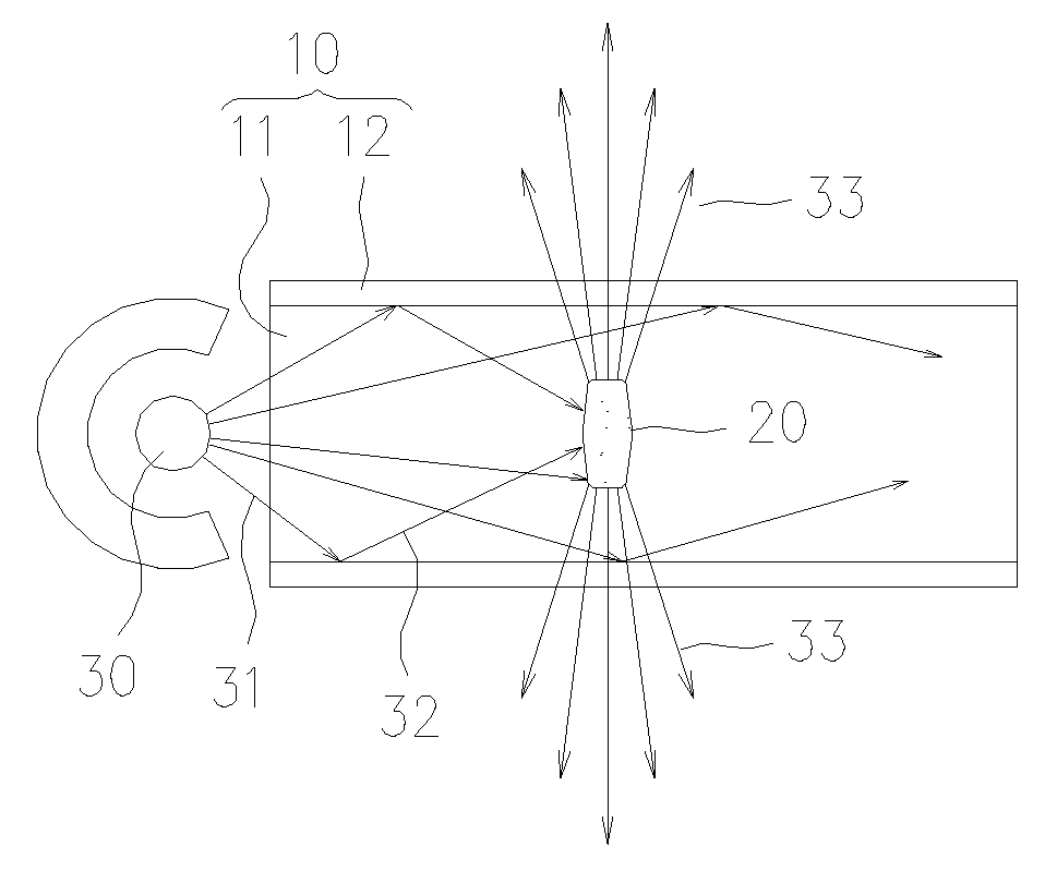
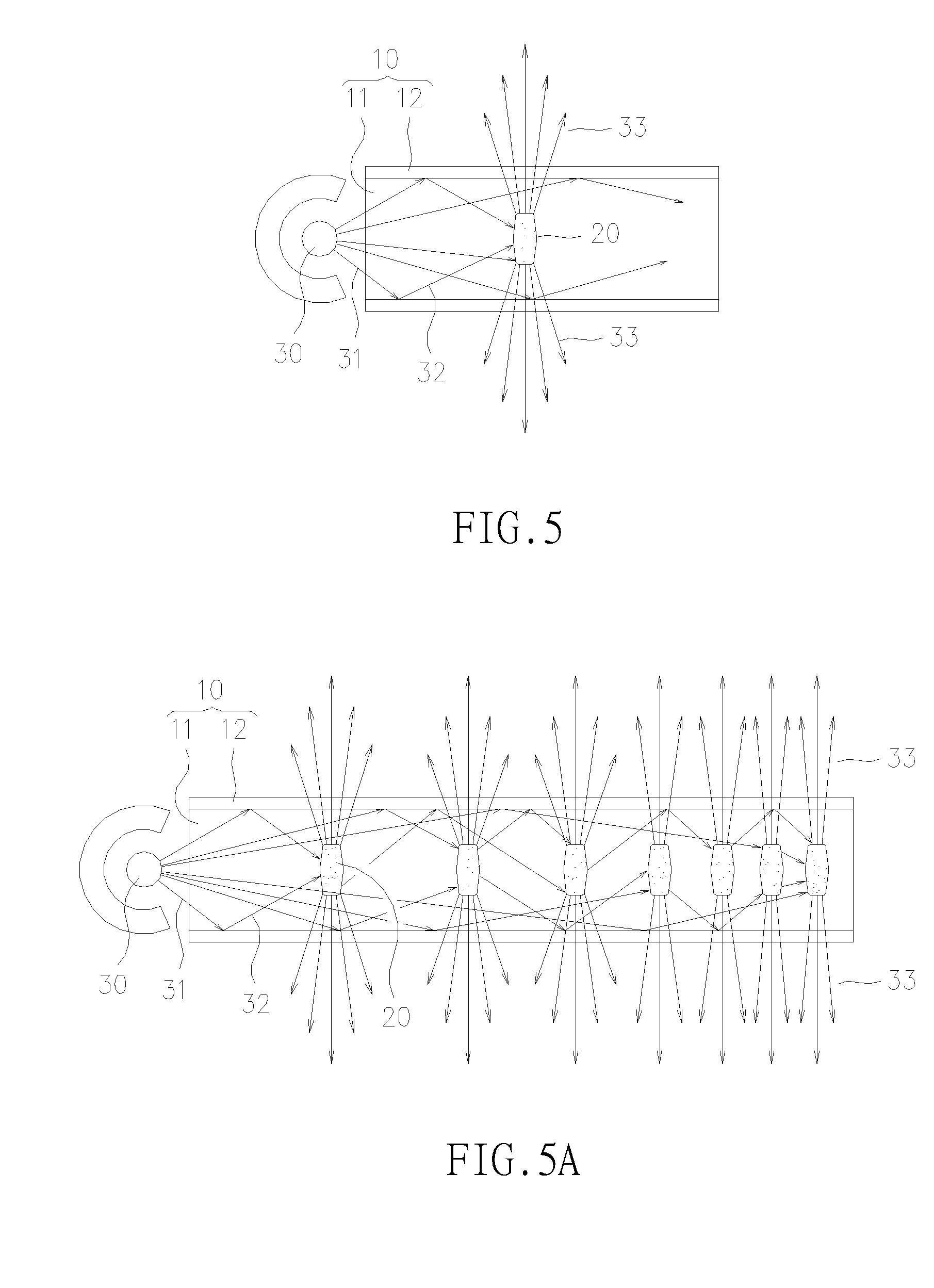
[0045]Please refer to FIG. 5, which shows an optical fiber having a microstructure formed therein according to a preferred embodiment of the invention. The purpose of forming the microstructure 20 inside the optical fiber 10 is to enable the optical fiber 10 to emit light radially from the side wall thereof. In FIG. 5, the optical fiber 10 is substantially composed of a core 11 wrapped by a cladding layer 12, that can be made of a transparent material, such as plastic, glass, quartz, etc., and can be cylindrical in shape, or other geometrical shapes at will. The microstructure 20 is arranged on the core 11 in a manner that the shape, quantity, size, distribution density and location are only dependent upon actual requirement ...


PUM

PropertyMeasurementUnit
widthaaaaaaaaaa
lengthaaaaaaaaaa
lengthaaaaaaaaaa

Abstract

An optical fiber is disclosed, which is comprised of: a core, having a plurality of microstructures formed thereon; and a cladding layer, surrounding the core. In a preferred embodiment, as light is transmitting along the axis of the aforesaid optical fiber and strikes on the plural microstructures, it is scattered and reflected out of the optical fiber through a side wall thereof so as to achieve a side-emitting effect. As the microstructures are formed inside the core of the aforesaid optical fiber, not only they are prevented from being damaged by normal usage, contacting to adhesive directly, but also they can lower the risk of the optical fiber being snapped/deformed while the optical fiber is subjecting to an external force and bended. In addition, by controlling the shape, quantity, size, distribution density and location of the microstructure, the brightness of the side-emitting optical fiber can be adjusted correspondingly.

Description

FIELD OF THE INVENTION[0001]The present invention relates to an improved optical fiber and the manufacturing method thereof, and more particularly, to an optical fiber having microstructures formed therein for blocking and scattering light traveling along its length and thus directing the light to emit radially from side walls of the optical fiber, in that each microstructures is a simple structure and can be formed inside the optical fiber by a simple manufacturing method without damaging the surface of the optical fiber, by which not only the risk of the optical fiber being snapped / deformed while the optical fiber is subjecting to an external force and bended is reduced, but also the light efficiency as well as the light uniformity of the optical fiber are improved.BACKGROUND OF THE INVENTION[0002]An optical fiber (or fiber optic) is a glass or plastic fiber designed to guide light along its length by total internal reflection, which is primarily composed of a core wrapped by a ca...

Claims


Application Information

Patent Timeline
Patent Type & Authority Applications(United States)
IPC IPC(8): F21V8/00C03C25/00G02B6/02
CPCG02B6/001C03C25/6233C03C25/6208
Inventor CHUANG, CHIA-CHENGHSIAO, CHUNG-HSIN
Owner IND TECH RES INST
Why Eureka
Try Eureka