Stack fastening device

a fastening device and fastening technology, applied in the direction of stacking articles, cell components, electrochemical generators, etc., can solve the problems of inability to use hydraulic cylinders at high temperatures, inability to smoothly flow electricity, and internal resistance generation, so as to achieve constant compressive force

Inactive Publication Date: 2008-07-03
DOOSAN HEAVY IND & CONSTR CO LTD
View PDF4 Cites 14 Cited by
  • Summary
  • Abstract
  • Description
  • Claims
  • Application Information

AI Technical Summary

Benefits of technology

[0013]Another object of the present invention is to provide a stack fastening device in which a spring box is installed on a base so that a shock-absorbing function can be provided to absorb the compressive force applied to a stack, whereby it is possible to flexibly deal even with situations in which the height of the stack and / or the compressive force applied to the stack is changed, and the compressive force can be kept constant.

Problems solved by technology

In the stack, since the plurality of unit cells is stacked upon one another, if a gap is formed between unit cells, problems are caused in that internal resistance is generated and the electricity cannot flow smoothly.
However since in the conventional stack fastening device, a hydraulic cylinder is fixedly installed on a stack, the hydraulic cylinder cannot be used at high temperatures such as 600° C., which is the operating temperature of the stack
Also, in the conventional stack fastening device, because the stack is held in a state in which it is simply locked between upper and lower plates after compression force is applied to the stack, the situation in which the height of the stack is changed cannot be flexibly dealt with.
Further, in the conventional stack fastening device, due to the fact that changes in the stack and the compressive force cannot be continuously monitored, it is difficult to adjust the magnitude of the compressive force applied to the stack.
As a consequence, in the conventional stack fastening device, because changes in the stack cannot be continuously monitored, in the case where the magnitude of the compressive force applied to the stack is increased, excessive force is applied to the stack and respective unit cells are likely to break.
Conversely, in the case where the magnitude of the compressive force is decreased, the contact force between the unit cells becomes insufficient and the smooth flow of electricity cannot be ensured, whereby the voltage cannot be supplied in an adequate manner.

Method used


Image

  • Stack fastening device
  • Stack fastening device
  • Stack fastening device

Examples


Embodiment Construction

[0031]Reference will now be made in greater detail to a preferred embodiment of the invention, an example of which is illustrated in the accompanying drawings. Wherever possible, the same reference numerals will be used throughout the drawings and the description to refer to the same or like parts.

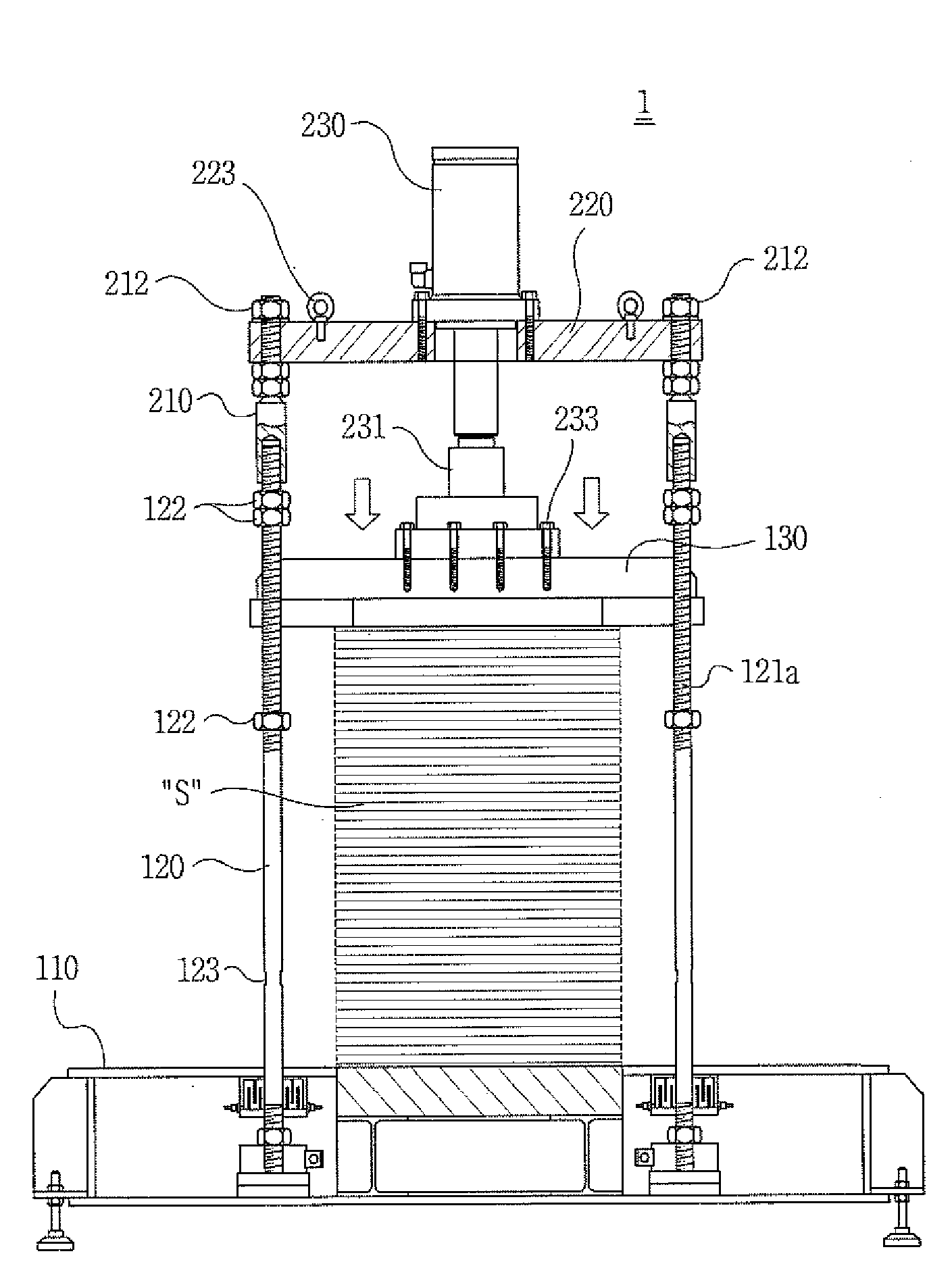
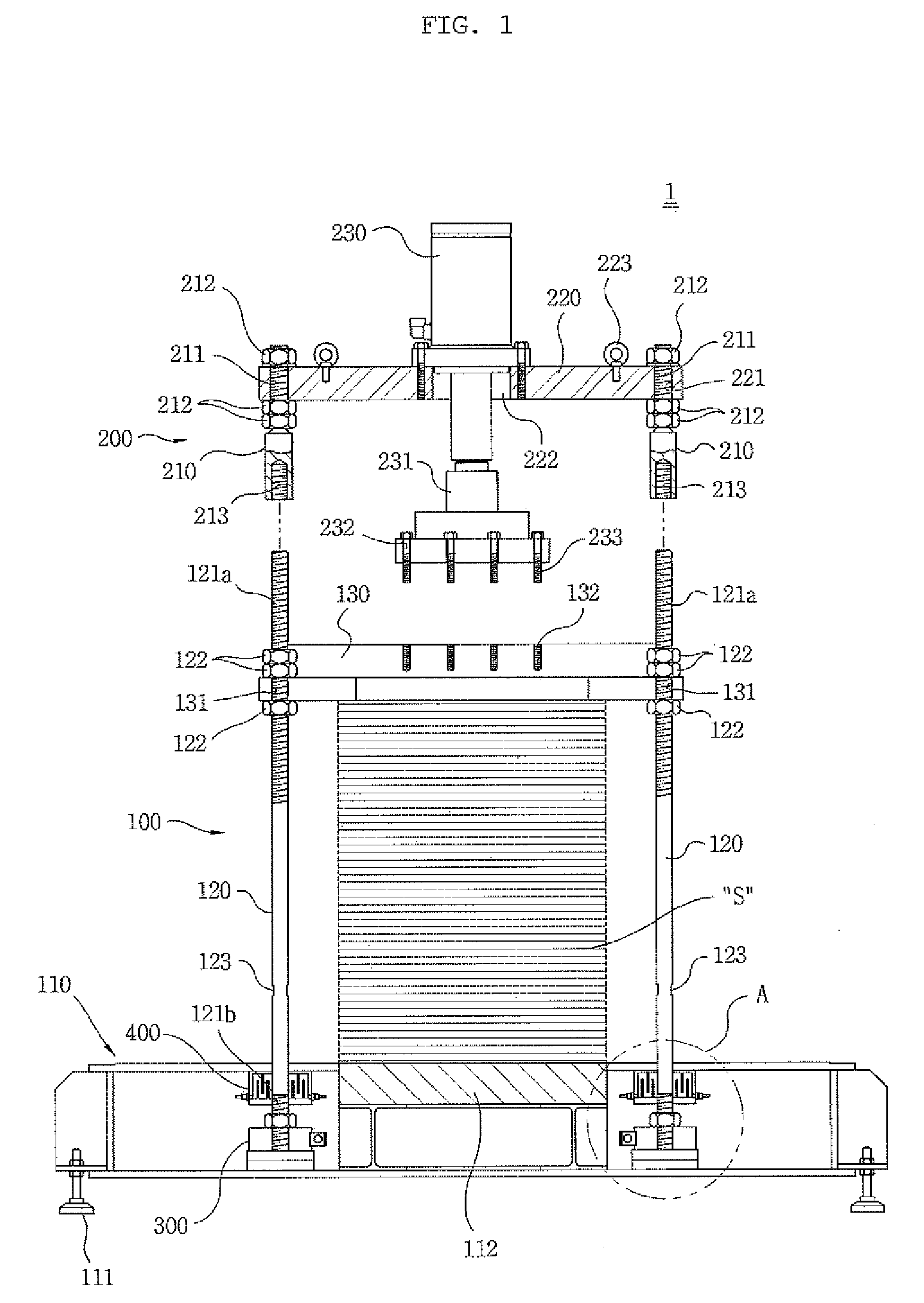
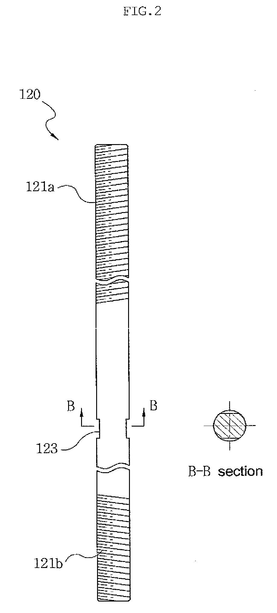
[0032]FIGS. 1 through 9 illustrate a stack fastening device in accordance with an embodiment of the present invention, wherein FIG. 1 is a partially exploded sectional view of the stack fastening device, FIG. 2 is a schematic view of a vertical beam, FIG. 3 is a partially broken-away front view of a connection beam, FIGS. 4 and 5 are sectional views illustrating states before and after a hydraulic unit according to the present invention is operated, FIG. 6 is an enlarged view of a part of FIG. 1, FIGS. 7 and 8 are sectional views illustrating variations of a flow path defined in a cooling unit, and FIG. 9 is a sectional view illustrating another assembly between a cooling unit and a load c...


PUM


Abstract

A stack fastening device includes a base, on an upper surface of which a stack is loaded, a compression plate, which has a flat configuration and is placed over the stack to press the stack, and a plurality of vertical beams, which are installed on the base to extend vertically so that the upper end portion of the beams projects out through the edge of the compression plate, A thread is formed in an upper end portion of each vertical beam, nuts are threadedly coupled to the thread such that the nuts can be tightened against upper and lower surfaces of the compression plate, and engagement grooves are defined in the upper surface of the compression plate so that a head of a hydraulic cylinder can be coupled to the compression plate.

Description

BACKGROUND OF THE INVENTION[0001]1. Field of the Invention[0002]The present invention relates to a stack fastening device for a molten carbonate fuel cell and, more particularly, to a stack fastening device in which a hydraulic unit is detachably installed on a stack fastening section and a load cell and a cooling unit are installed on the lower end of a vertical beam so that compressive force can be applied using a hydraulic cylinder and changes in a stack and in compressive force can be continuously monitored.[0003]2. Description of the Prior Art[0004]As is generally known in the art, a fuel cell serves as an electric power generation device for converting chemical energy, obtained through the oxidation and reduction of a reactant, into electrical energy. In the fuel cell, only water is discharged as a byproduct, unlike other existing kinds of chemical energy. Therefore, since the fuel cell does not cause any environmental pollution, does not generate noise, and features a simple ...

Claims


Application Information

Patent Timeline
Patent Type & Authority Applications(United States)
IPC IPC(8): B65B35/36
CPCH01M8/244H01M8/248Y02E60/526Y02E60/50H01M2008/147H01M8/24
Inventor KANG, DONG WOOCHANG, IN GABPARK, JONG SEUNGLEE, TAE WON
Owner DOOSAN HEAVY IND & CONSTR CO LTD
Why Eureka
Try Eureka