Osseonitegrated limb prosthesis

a limb prosthesis and osseonite technology, applied in the field of osseonitegration, can solve the problems of inability to achieve the so-called pumping effect, wear and damage of tissues, and inability to move between soft tissues and the bones of the user's stump

Active Publication Date: 2008-07-03
OSSUR HF
View PDF6 Cites 20 Cited by
  • Summary
  • Abstract
  • Description
  • Claims
  • Application Information

AI Technical Summary

Benefits of technology

[0012]An object of the present invention is to provide an limb prosthesis having most of the advantages of osseointegrated prostheses but which reduces transfer of bending and / or rotational forces to the implant, which will enable a higher loading of the prosthesis, especially in the form of bending and / or rotational forces, and thus will enable a higher maximum activity level for the prosthesis wearer. These and further objects have according to the invention been achieved by a limb prosthesis which via coupling means is adapted to be connected to an implant in the form of an osseointegrated shaft projecting from an amputated stump, said coupling means comprises a flexible joint and said prosthesis further comprises a force transmitting device secured to and extending from a prosthetic member connected to the coupling means up to a position on the amputated stump or body portion to which the stump connects. The force transmitting device is adapted to be secured to the stump or other body portion in such a way that it relieves the implant from at least part of the bending and / or rotational forces exerted to the prosthetic member.
[0019]In one aspect of the invention the coupling means is adapted to prevent tilting movement of the implant with respect to the prosthetic member connected thereto.
[0020]In a further aspect of the invention the said coupling means is adapted to prevent relative rotational movement of the implant with respect to the prosthetic member connected thereto.
[0021]In a still further aspect of the invention the coupling means is adapted to prevent relative axial movement of the implant with respect to the prosthetic member connected thereto.

Problems solved by technology

Especially for leg prostheses, which have to carry the body weight of the user, this results in a non-desired so called pumping effect, which means that the soft tissues on the stump inserted into the socket will be pressed together when loaded and be extended when unloaded.
In other words there will be an undesired relative movement between the soft tissues and the bones of the user's stump.
This pumping effect causes wear and damage of the tissues.
It further results in instability, which may cause a risk for stumbling and leads to a compensating gait with hip-hiking.
The gait is more energy consuming and causes stress on the hip, foot and back.
It further leads to a low perception for motion and position of the prosthesis.
The disadvantages are that the rehabilitation period is lengthy since it takes a long time to obtain the necessary strength in the implant in order to be able to put a load on it and an even longer time to reach the maximum activity level.
Maximum activity level is still limited and the wearer is for example not recommended to run.
A high activity level involves a risk for damage on the part of the implant penetrating the skin, the so called abutment, the bone to which the implant is attached or the metal components adjoining to the implant.
It however has a much lower strength when exerted to torsional and bending moments.
This is the reason why the freedom of movement for an osseointegrated leg prosthesis is limited and that the user is for example not recommended to run.
This pressure pad may take up tensile and pressure forces but is not adapted to take up any bending or rotational forces.

Method used


Image

  • Osseonitegrated limb prosthesis
  • Osseonitegrated limb prosthesis
  • Osseonitegrated limb prosthesis

Examples


Embodiment Construction

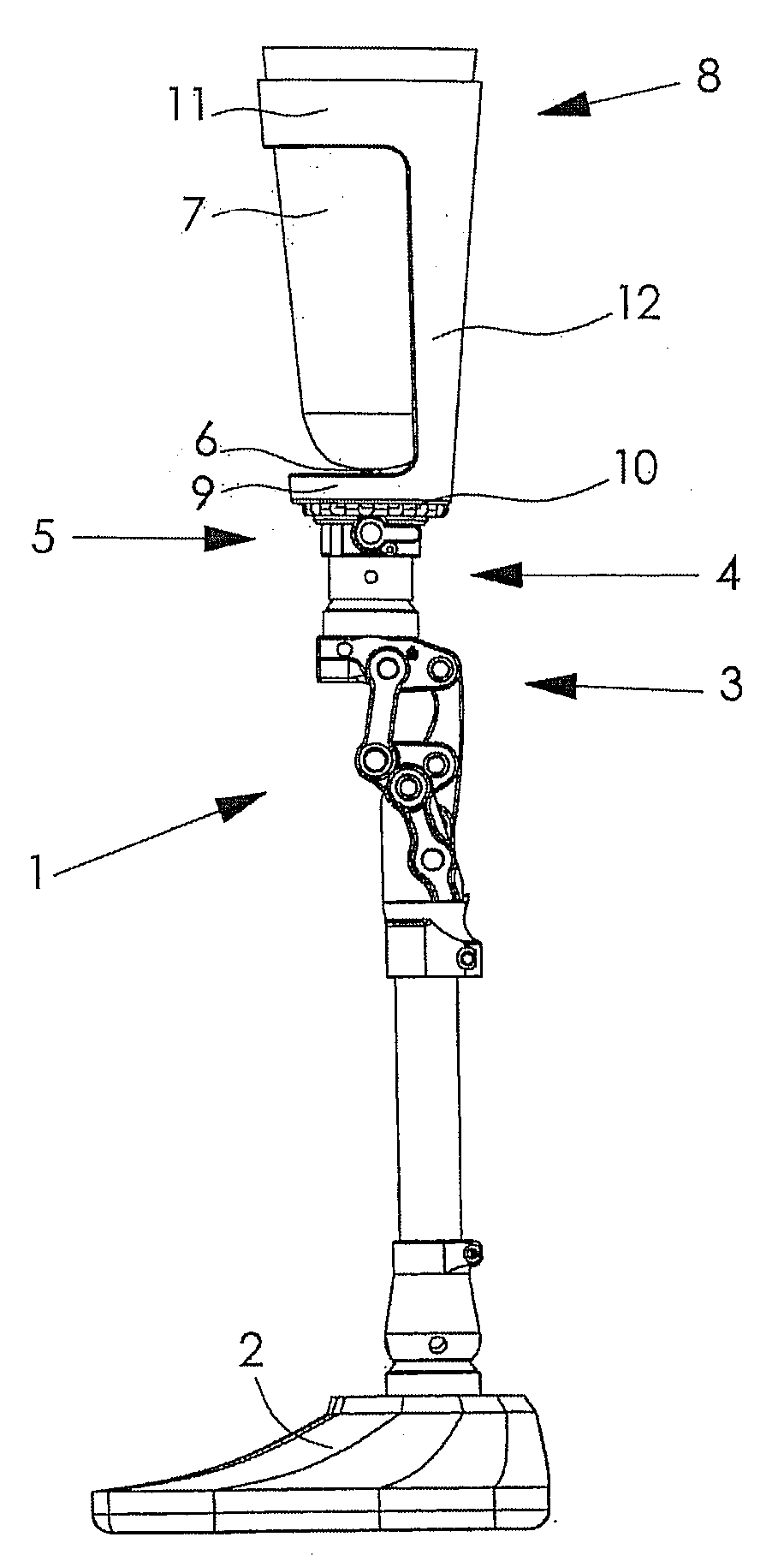
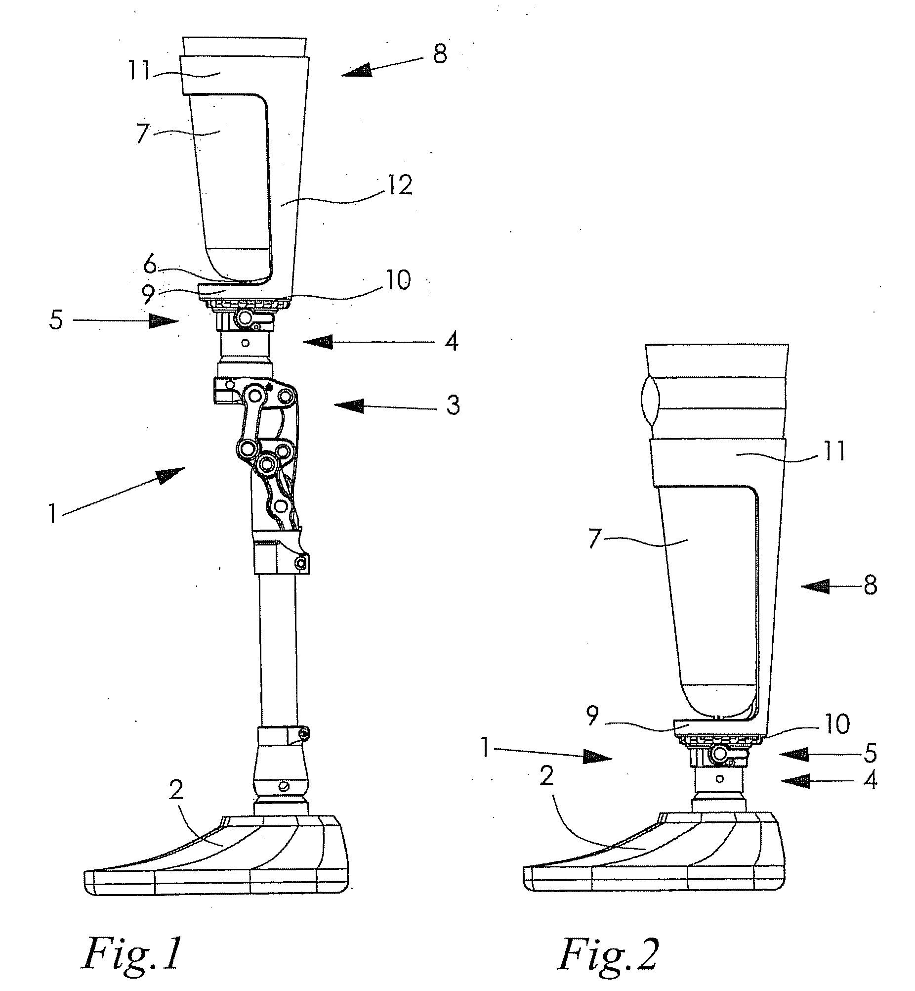
[0033]FIG. 1 shows an above knee amputation comprising a leg prosthesis 1, comprising a prosthetic foot 2, a prosthetic knee 3 and various adjustable connecting couplings. The prosthetic knee shown in the drawings is of a type disclosed in U.S. Pat. No. 6,808,540 and will not be further described. A prosthetic member 4, which according to FIG. 1 constitutes a part of the upper leg prosthesis is via coupling means 5 connected to an implant 6 in the form of an osseointegrated shaft, for example a titanium screw. The implant 6 is integrated into the skeleton of an amputated stump 7.

[0034]The stump 7 is held in a socket 8, which in a manner described more in detail below will relieve the implant 6 from at least part of the bending and / or rotational forces exerted to the prosthetic member 4. Such forces will instead be transferred via the socket 8, which acts as a force transmitting device. The socket 8 has one end portion 9 secured to a connector sleeve 10 of the prosthetic member 4 and...


PUM


Abstract

A limb prosthesis which via coupling means is adapted to be connected to an implant in the form of an osseointegrated shaft projecting from an amputated stump. The coupling means comprises a flexible joint and the prosthesis further comprises at least one force transmitting device secured to and extending from a prosthetic member connected to the coupling means up to a position on the amputated stump or body portion to which the stump connects. The force transmitting device is adapted to be secured to the stump or other body portion in such a way that it relieves the implant from at least part of the bending and / or rotational forces exerted to the prosthetic member.

Description

TECHNICAL FIELD[0001]The present invention refers to a limb prosthesis which via coupling means is adapted to be connected to an implant in the form of an osseointegrated shaft projecting from an amputated stumpBACKGROUND OF THE INVENTION[0002]Traditional prostheses, leg prostheses as well as arm prostheses, use a socket for connecting the prosthesis to the body. The socket is applied onto the remaining part of the user's limb, the so called “stump”. This means that the transmission of forces between the prosthesis and the user takes place via the remaining soft tissues on the stump. Especially for leg prostheses, which have to carry the body weight of the user, this results in a non-desired so called pumping effect, which means that the soft tissues on the stump inserted into the socket will be pressed together when loaded and be extended when unloaded. In other words there will be an undesired relative movement between the soft tissues and the bones of the user's stump.[0003]This ...

Claims


Application Information

Patent Timeline
Patent Type & Authority Applications(United States)
IPC IPC(8): A61F2/60A61F2/80
CPCA61F2/30749A61F2230/0071A61F2/76A61F2/78A61F2002/30242A61F2002/30364A61F2002/30367A61F2002/3037A61F2002/30434A61F2002/30476A61F2002/3051A61F2002/30512A61F2002/3485A61F2002/503A61F2002/5043A61F2002/5098A61F2002/6854A61F2002/7887A61F2220/0025A61F2220/0033A61F2220/0041A61F2/60A61F2002/30433A61F2002/30507
Inventor GRAMNAS, FINN
Owner OSSUR HF
Why Eureka
Try Eureka