Environmental control and power system

a technology of environmental control and power system, applied in the direction of instruments, heating types, static/dynamic balance measurement, etc., can solve the problem of inability to effectively operate a medical unit, and achieve the effect of reducing external thermal signature, dissipating heat, and reducing acoustic nois

Inactive Publication Date: 2008-07-03
GLACIER BAY
View PDF13 Cites 142 Cited by
  • Summary
  • Abstract
  • Description
  • Claims
  • Application Information

AI Technical Summary

Benefits of technology

[0012]In another exemplary embodiment of the present invention, there is an ECAPS unit as described above or below, wherein the first inverter assembly transforms the first DC power to the export AC power such that the export AC power is a sine wave at least one of 115, 120, 220, 230 and 240 volts and at least one of about 50 hz, 60 hz and 400 hz. In another exemplary embodiment of the present invention, there is an ECAPS unit as described above or below, wherein the HVAC has a capacity of 0-40 kw in heating mode and 5,000-to 60,000 BTU / hr in cooling mode. In another exemplary embodiment of the present invention, there is an ECAPS unit as described above or below, further comprising a liquid-air heat exchanger adapted to dissipate heat from the engine and the first generator so as to decrease the external thermal signature of the ECAPS unit, wherein heated components of the heat exchanger are radiatively shielded from the outside of the ECAPS unit and the ECAPS unit is adapted to direct cooling air discharged from the heat exchanger in a manner to prevent external components of the ECAPS unit from heating above an ambient temperature due to the discharged cooling air.
[0013]In another exemplary embodiment of the present invention, there is an ECAPS unit as described above or below, further comprising an exhaust system configured to exhaust combustion gases from the diesel engine in a manner that decreases acoustic noise and decreases the external thermal signature of the ECAPS unit, wherein heated components of the exhaust system are radiatively shielded from the outside of the ECAPS unit and the ECAPS unit is adapted to discharge combustion gases exhausted from the ECAPS unit in a manner to prevent external components of the ECAPS unit from heating above an ambient temperature due to the discharged combustion gases.

Problems solved by technology

In many areas, the effective operation of a medical unit is not possible due to extreme environmental conditions.

Method used


Image

  • Environmental control and power system
  • Environmental control and power system
  • Environmental control and power system

Examples


Embodiment Construction

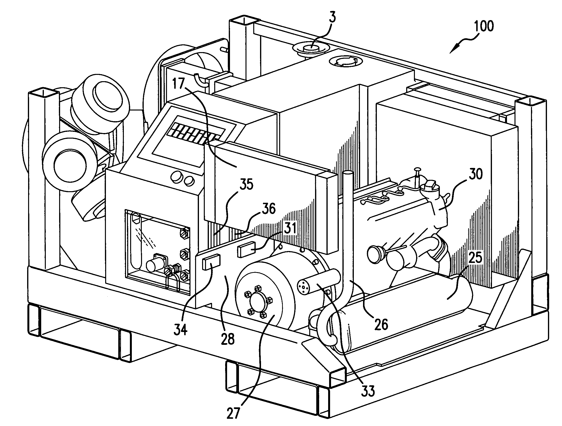
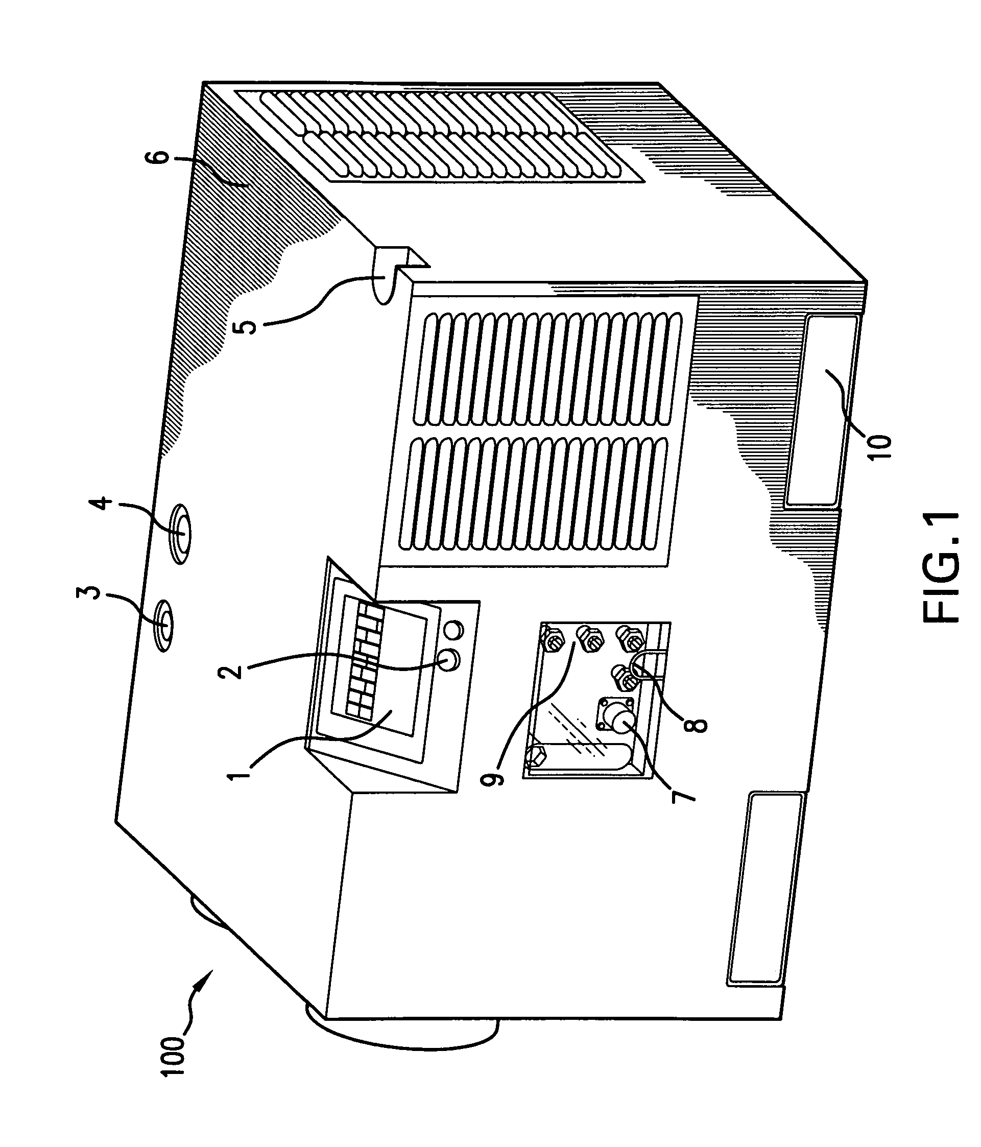
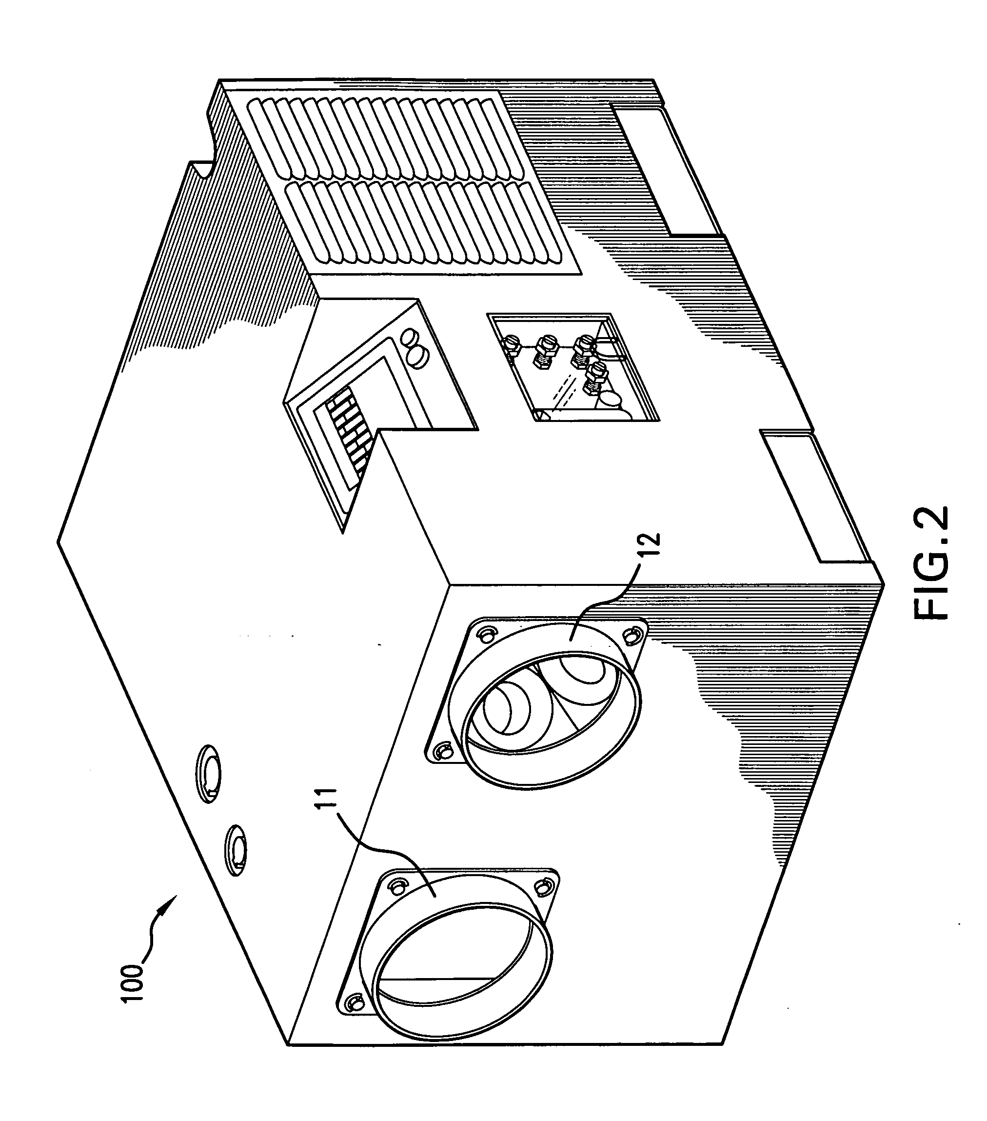
[0030]Referring now to FIGS. 1-4, a first embodiment of an Environmental Control And Power System (ECAPS) unit according to an exemplary embodiment of the present invention may be seen. In the embodiments depicted in FIGS. 1-4, the ECAPS unit includes a variable-speed diesel engine 30 and an HVAC system 110 which are supported by a frame 23. In the embodiments presented in FIGS. 1-4, the HVAC system 110 is powered by a generator 27 that is mechanically coupled to the diesel engine 30, the generator 27 producing electrical power which is in turn is used to power the HVAC system 110. According to the embodiments depicted in the figures, the HVAC system 110, the generator 27 and the diesel engine 30 are all packaged in a self-contained unit (the ECAPS unit 100).

[0031]In the embodiments depicted in FIGS. 1-4, the generator 27 is an alternator that outputs AC power at variable frequency. The ECAPS unit includes a rectification assembly 31 which transforms the AC power outputted from the ...


PUM


Abstract

A self-contained environmental control and power system (ECAPS) unit including an HVAC system with at least one variable-speed compressor driven by a DC motor, wherein the HVAC system is adapted to condition air and output the conditioned air and a variable-speed diesel engine connected to a generator. The generator is configured to vary in speed so as to output AC power at a variable frequency. The unit includes a rectification assembly which transforms the AC power from the generator and/or external AC power to DC power, and an inverter assembly which transforms the DC power to an export AC power. The ECAPS unit directs the DC power to the DC motor to drive the variable speed compressor and varies, in a controlled manner, at least one parameter of the outputted conditioned air from the HVAC system.

Description

CROSS-REFERENCE TO RELATED PATENT APPLICATIONS[0001]This application claims priority to U.S. Provisional Application 60 / 822,717, filed Aug. 17, 2006, the contents of which are incorporated herein by reference in its entirety.BACKGROUND OF THE INVENTION[0002]Military and other emergency response services often need to quickly establish temporary hospital and first-aid shelters to treat injuries on location before patients are transported to more permanent care facilities. These shelters are typically tents or similar poorly insulated habitats that, when located in extremely hot, cold or humid environments, sometimes present an inhospitable environment for the occupants. In many areas, the effective operation of a medical unit is not possible due to extreme environmental conditions.[0003]Typically, in areas where such shelters are provided, there also exists a need to provide electrical power for lights, computers, communication equipment and medical equipment inside the shelter. Inde...

Claims


Application Information

Patent Timeline
Patent Type & Authority Applications(United States)
IPC IPC(8): F24F11/00F04B17/00G05D23/19F24F1/02
CPCF04B35/00F25B27/00Y02B30/741F25B2600/0253F25B2327/001Y02B30/70
Inventor ALSTON, GERALD ALLEN
Owner GLACIER BAY
Why Eureka
Try Eureka