

Wheel Control Device and Control Device
a control device and control device technology, applied in the direction of process and machine control, braking systems, instruments, etc., can solve problems such as reducing vehicle stability, and achieve the effect of suppressing the reducing of vehicle stability during wheel driving
- Summary
- Abstract
- Description
- Claims
- Application Information
AI Technical Summary
Benefits of technology
Problems solved by technology
Method used
Image

Examples
first embodiment
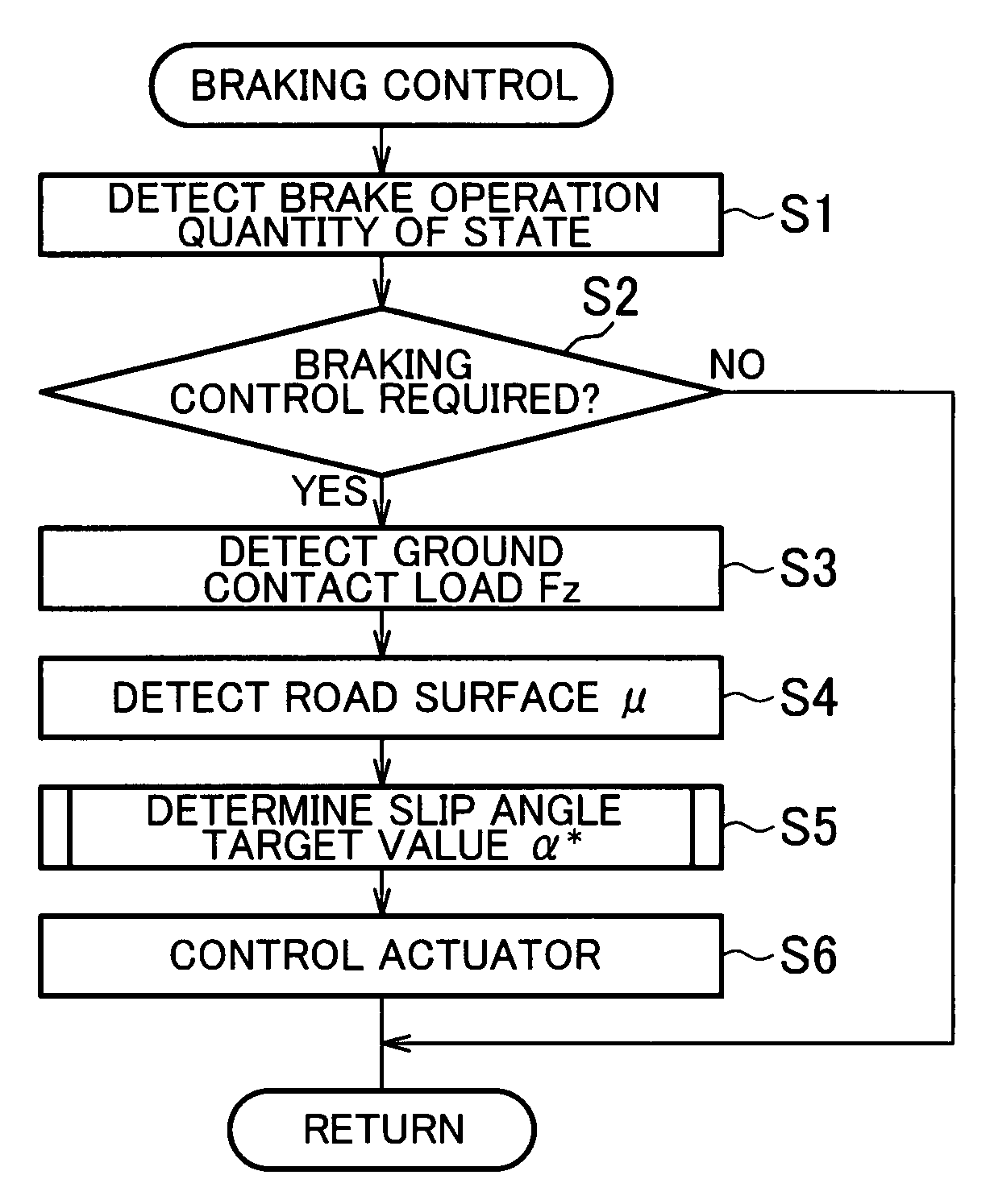
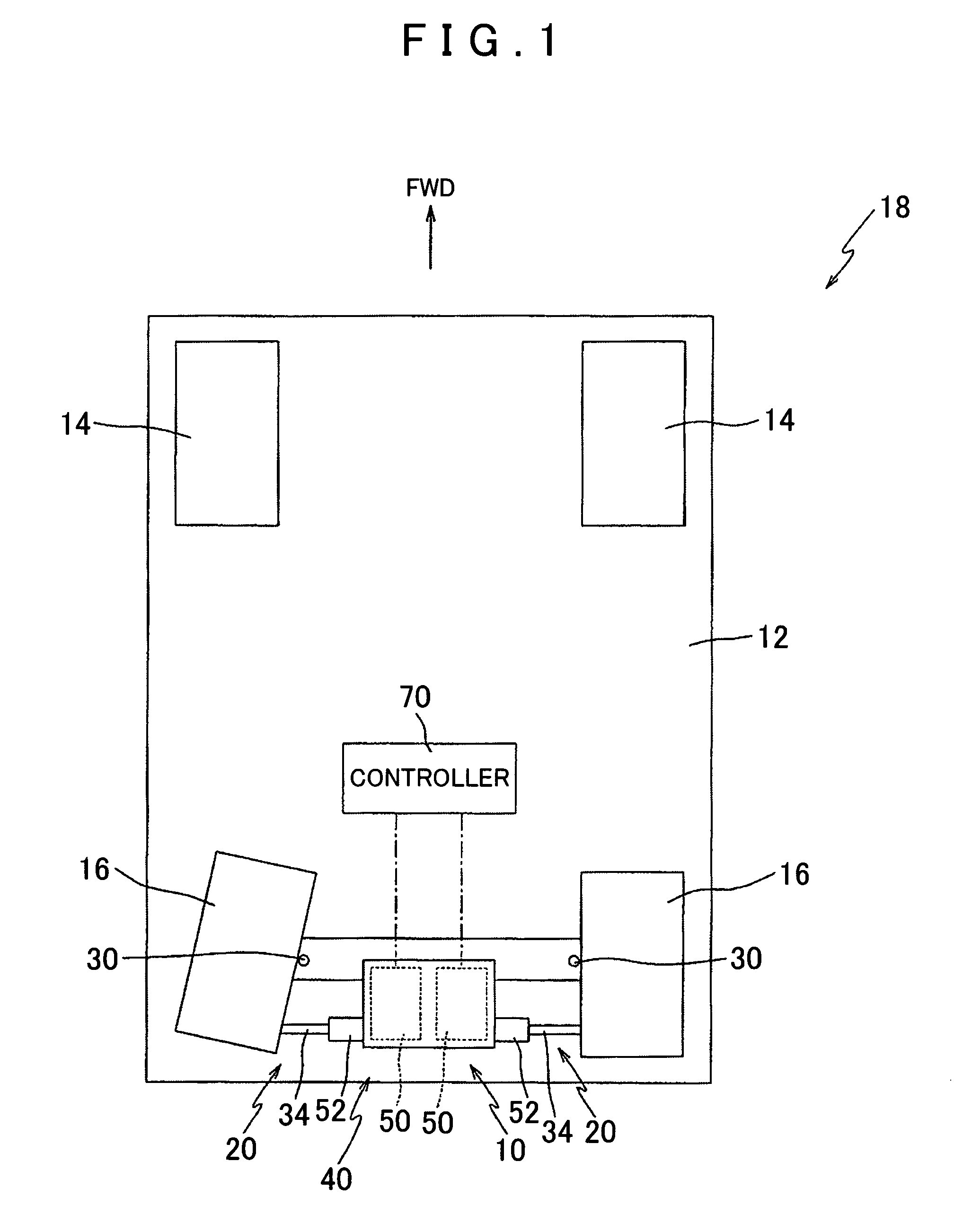
[0125]FIG. 1 is a plan view showing a wheel control device 10 according to the present invention. The wheel control device 10 is installed and used in a vehicle 18 formed by attaching a plurality of wheels 14, 16 to a vehicle body 12. As shown in FIG. 1, an example of the vehicle 18 has left and right front wheels 14, 14 and left and right rear wheels 16, 16.
[0126]In the vehicle 18, the left and right front wheels 14, 14 are steered by a steering mechanism, not shown in the drawing, in accordance with a steering operation performed by a driver on a steering wheel, not shown in the drawing. In this embodiment, the left and right rear wheels 16, 16 are attached to the vehicle body 12 via respective steering devices 20, 20. The wheel control device 10 is installed in the vehicle 18 to control the left and right rear wheels 16, 16 independently of one another in relation to a slip angle α. In FIG. 1, the left and right rear wheels 16, 16 are illustrated in attitudes having different sli...
third embodiment
[0244]In the third embodiment, the wheel 2 is driven to rotate by the wheel driving device 3 and the peripheral velocity Vr (rotation speed) of the wheel 2 is controlled regardless of the slip angle θ of the wheel 2, but the present invention is not limited thereto. For example, the wheel 2 may be driven to rotate by the wheel driving device 3 only when the slip angle θ of the wheel 2 exceeds a reference magnitude.
[0245]FIG. 16 is a view showing a relationship between the slip angle θ of the wheel 2 and a rotation speed r of the freely rolling wheel 2. As shown in FIG. 16, to ensure that the wheel 2 rolls freely (as described above, free rolling is a state in which no slippage occurs between the wheel 2 and the road surface), the rotation speed of the wheel 2 must be raised as the slip angle θ increases.
[0246]More specifically, the rotation speed r of the freely rolling wheel 2 is r=r0 / cos θ relative to a rotation speed r0 when the slip angle θ=0. Hence, as shown in FIG. 16, in rela...
fourth embodiment
[0375]Further, in the fourth embodiment, a case in which the absolute values of the steering angle and camber angle of each wheel 2 is determined in proportion to the operation amount (depression amount) of the brake pedal 252 by the driver was described (see FIG. 21), but the present invention is not limited thereto, and needless to say, the steering angle and camber angle of each wheel 2 may be determined on the basis of another quantity of state.
[0376]Examples of this other quantity of state include the operation speed of the brake pedal 252 and the deceleration of the vehicle 4001. For example, control may be performed to increase (decrease) the steering angle and camber angle when the operating speed of the brake pedal 252 is higher (lower) than a reference value in relation to a constant depression amount.
[0377]Further, control may be performed to increase (decrease) the steering angle and camber angle when the deceleration of the vehicle 4001 is higher (lower) than a referenc...
PUM
 Abstract
Description
Claims
Application Information