Binary Logic Unit and Method to Operate a Binary Logic Unit

Inactive Publication Date: 2008-07-03
IBM CORP
View PDF3 Cites 0 Cited by
  • Summary
  • Abstract
  • Description
  • Claims
  • Application Information

AI Technical Summary

Benefits of technology

[0008]It is therefore an object, of at least one embodiment, of the invention to provide a binary logic unit with reduced silicon area requirement consequence of which is a reduced power consumption and leakage power. It is also an object of the invention to provide a method to operate such a binary logic unit.

Problems solved by technology

Thereby in modern microprocessors power consumption particularly due to leakage power is a huge problem and is to be reduced.
The larger the silicon area required, the higher the leakage power suffered.

Method used


Image

  • Binary Logic Unit and Method to Operate a Binary Logic Unit
  • Binary Logic Unit and Method to Operate a Binary Logic Unit
  • Binary Logic Unit and Method to Operate a Binary Logic Unit

Examples


Embodiment Construction

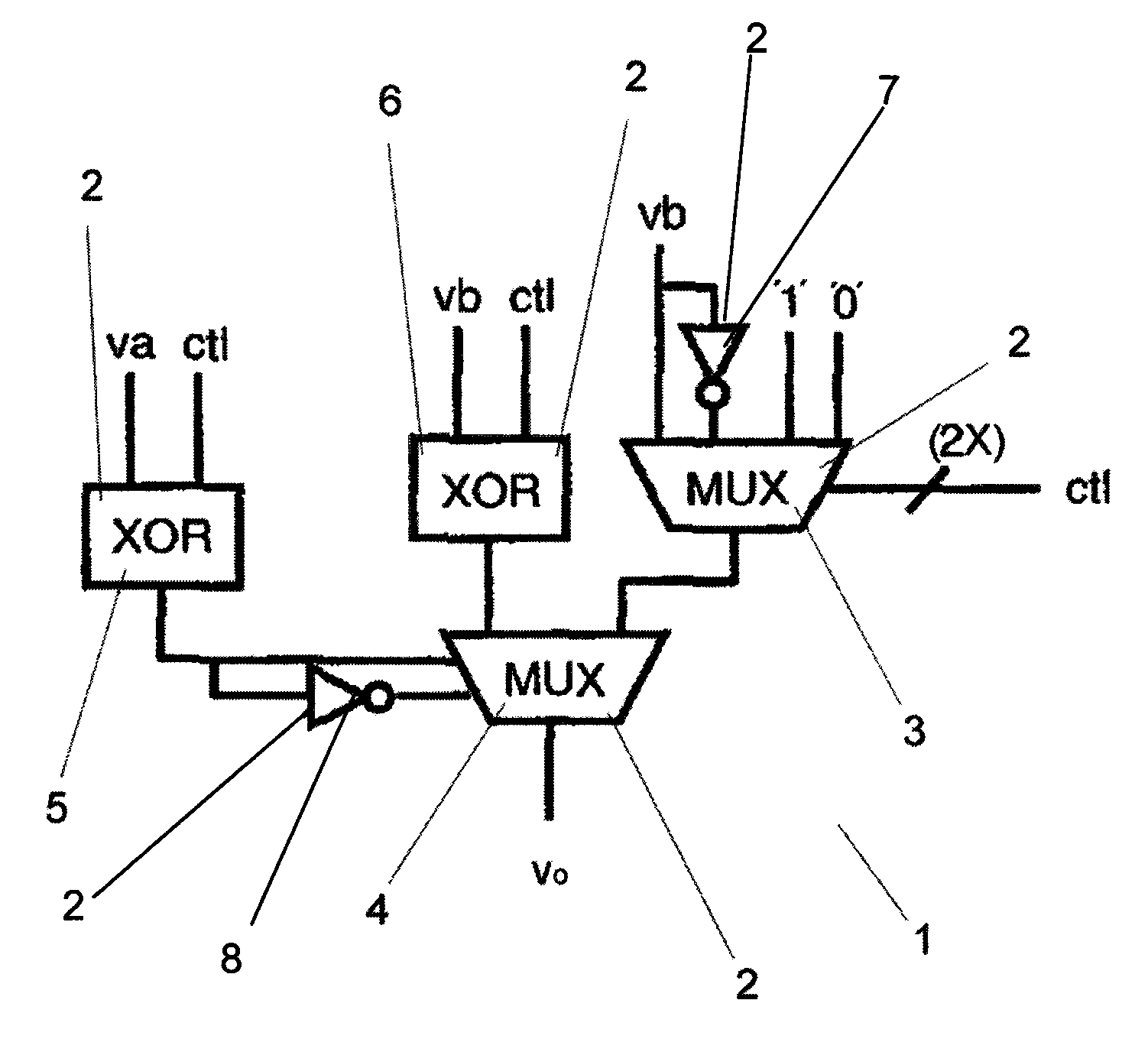
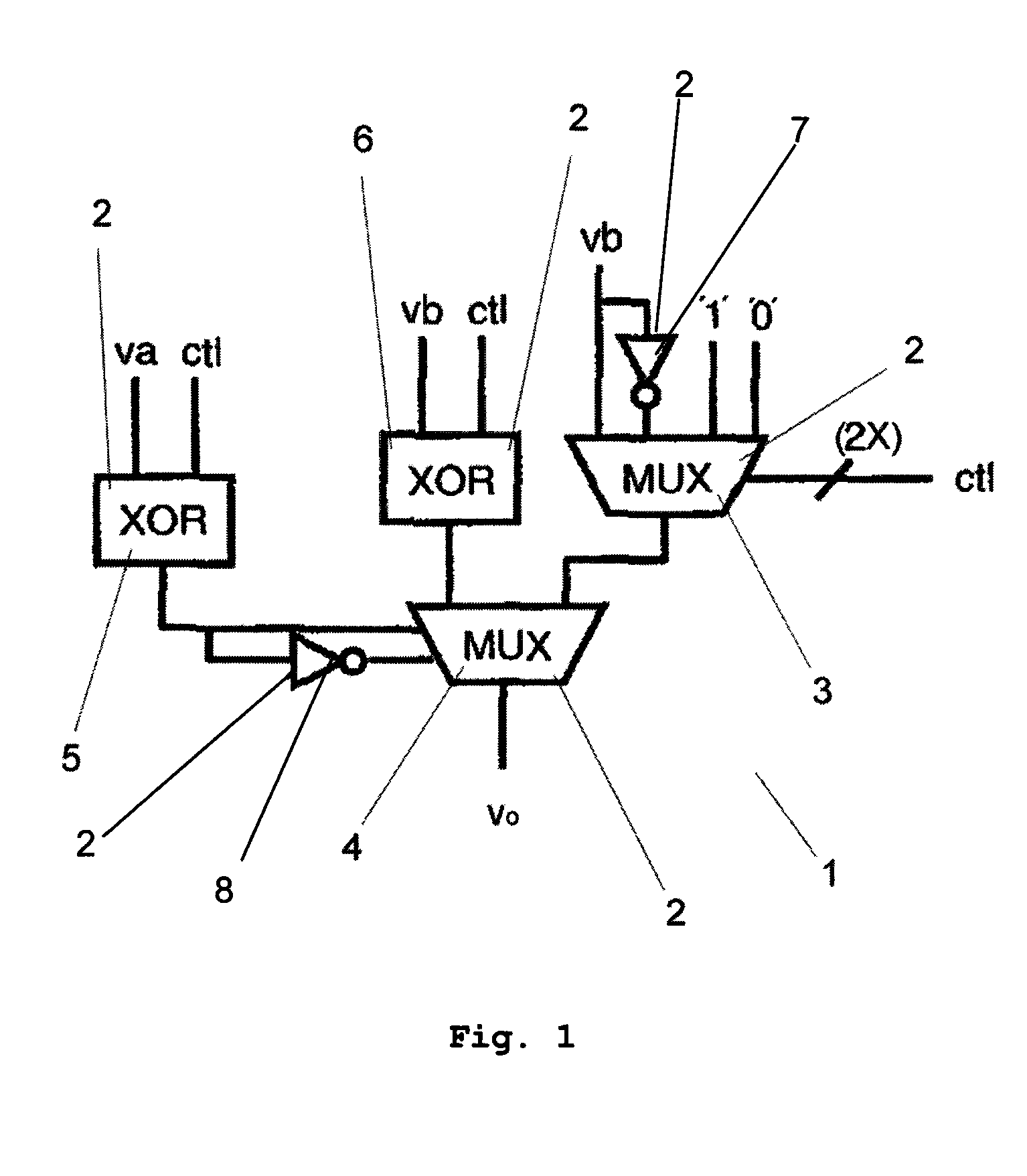
[0035]In a binary logic unit according to the invention, any desired Boolean operation to be applied on the input signals of the binary logic unit is defined by a particular combination of well defined control signals that are fed into the binary logic unit. The input signals are used to select one control signal of a particular combination of control signals that define a particular desired Boolean operation to be applied on the input signals as an output signal of the binary logic unit. The selected control signal that is the output signal represents the result of the particular Boolean operation applied on the two input signals. The binary logic unit according to the invention works according to a multiplexer principle. Thereby data and control inputs of the multiplexer are interchanged in a way that the input signals are applied on the control inputs of the multiplexer and the control signals are applied on the data inputs of the multiplexer. Depending on a desired Boolean opera...


PUM


Abstract

A binary logic unit to apply any Boolean operation on two input signals (va, vb) is described, wherein any Boolean operation to be applied on the input signals (va, vb) is defined by a particular combination of well defined control signals (ctl0, ctl1, ctl2, ctl3), wherein the input signals (va, vb) are used to select a control signal (ctl0, ctl1, ctl2, ctl3) as an output signal (vo) of the binary logic unit representing the result of a particular Boolean operation applied on the two input signals (va, vb). Furthermore a method to operate such a binary logic unit is described.

Description

BACKGROUND OF THE INVENTION[0001]The invention relates to a binary logic unit to apply any desired Boolean operation on two input signals plus a method to operate such a binary logic unit.[0002]A binary logic unit used to apply logic Boolean operations on two input signals va, vb comprises a plurality of basic logic gates like AND, OR, XOR and XNOR gates, each one consisting of one or more transistors. Table 1, shown in FIG. 8, gives an overlook over the Boolean operations that can be performed on two input signals va, vb by a binary logic unit.[0003]A binary logic unit 1 according to the state of the art is shown in FIG. 1. It is a static CMOS realization of thirty-eight transistors that are arranged to different logic gates 2. The logic gates 2 are a 4:1 multiplexer 3, a 2:1 multiplexer 4, two XOR-gates 5, 6, and two inverters 7, 8. The logic gates 2 are controlled by control signals ctl switching the transistors of the logic gates 2 in a way that an output signal vo of the binary...

Claims


Application Information

Patent Timeline
IPC IPC(8): G06F9/305
CPCG06F7/00H03K19/20G06F9/30029
Inventor GEMMEKE, TOBIASPREISS, JOCHEN
Owner IBM CORP
Why Eureka
Try Eureka