
Method of maintaining traffic services through congestion caused by network failovers

a traffic service and network failover technology, applied in the field of communication systems, can solve problems such as network congestion, drop calls, and congestion in forwarding data packets over that hop, and achieve the effect of accurately determining whether a failover operation is necessary

Inactive Publication Date: 2008-07-03
RPX CORP +1
View PDF3 Cites 25 Cited by
  • Summary
  • Abstract
  • Description
  • Claims
  • Application Information

AI Technical Summary

Benefits of technology

[0008]Thus, in cases where a standard control mode would automatically drop calls to alleviate failover congestion, the system of the present invention recognizes that such dropped calls are in most case unnecessary. Data traffic is controlled to account for failover congestion in a manner that reduces or eliminates the need for call drops, with network traffic being maintained to the maximum extent possible. (Although network transmissions are sometimes characterized in the industry as either voice or data transmissions, “data” and “data traffic” refer herein to any packet-based or other network traffic in a general sense, and not just to non-voice data.)
[0010]In another embodiment, the failover indicators generated by the monitored network entities are correlated or cross-referenced to a time scale of data transfer over the network. In other words, each indicator, besides being associated with a particular network entity (or group of entities) and / or other data relating to the nature of the indicator, is associated with a time of when the indicator occurred, relative to the other indicators. One or more filters process the indicator data for determining if a failover operation has occurred, e.g., the filters are part of the software / hardware agents, and / or work in conjunction therewith. (By “determine,” it is meant not an absolute determination, but rather a determination within a range of acceptable error, e.g., a prediction or approximation.) By taking into account both L1 and L2 indicators across a time period of interest, it is possible to more accurately determine whether a failover operation has occurred, as opposed to relying on L1 indicators alone (e.g., DS1 alarms), which may be filtered out by certain network entities.

Problems solved by technology

Although failover operations preserve overall network integrity by maintaining communications across the network, in certain systems they may result in network congestion, a decrease in data throughput, dropped calls, and the like.
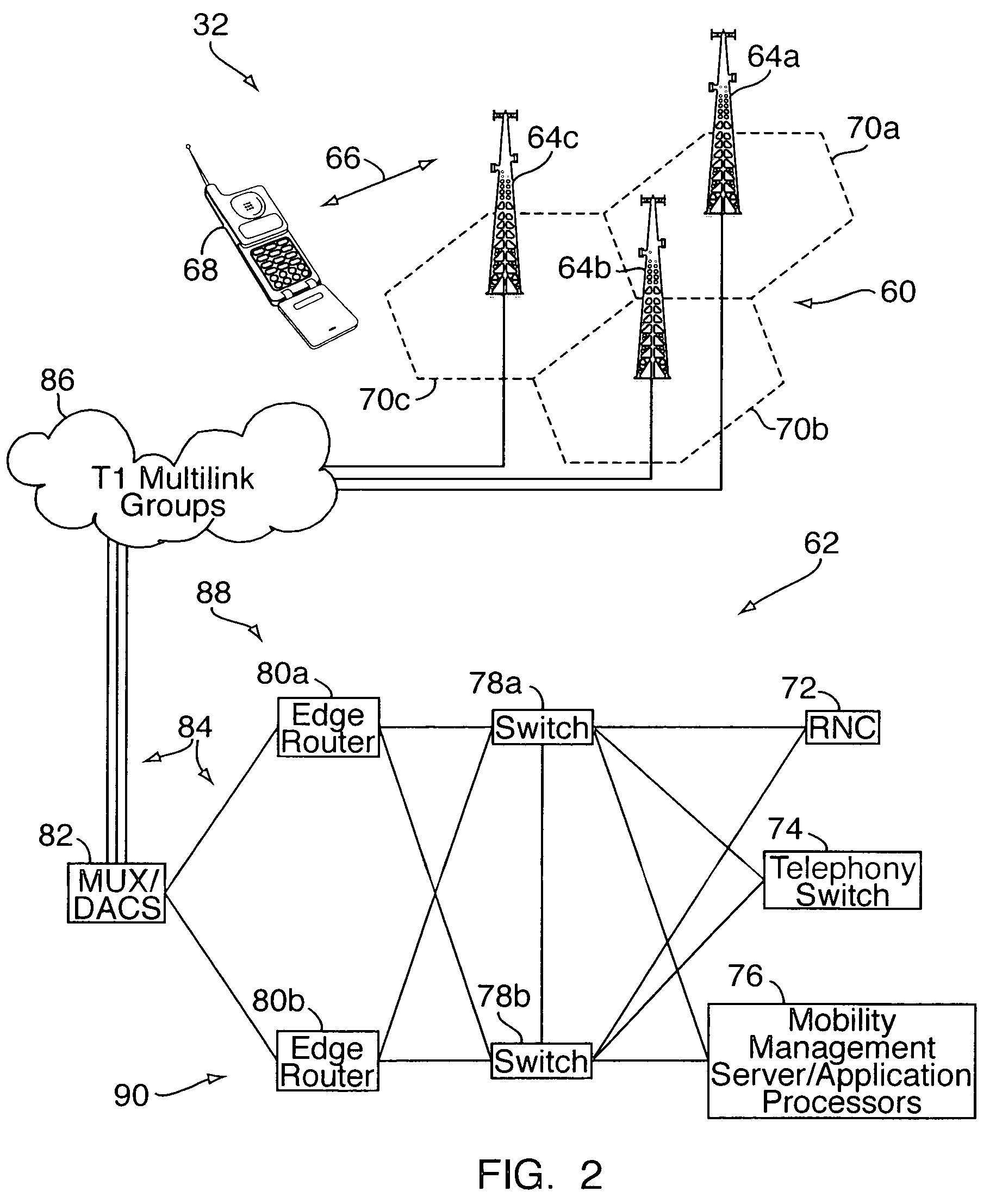
Failure in a multilink group (a multilink group is a set or grouping of data links or nodes) typically causes congestion in forwarding data packets over that hop, including the delay of time sensitive air interface data.
Such congestion can last much longer than the network can support.
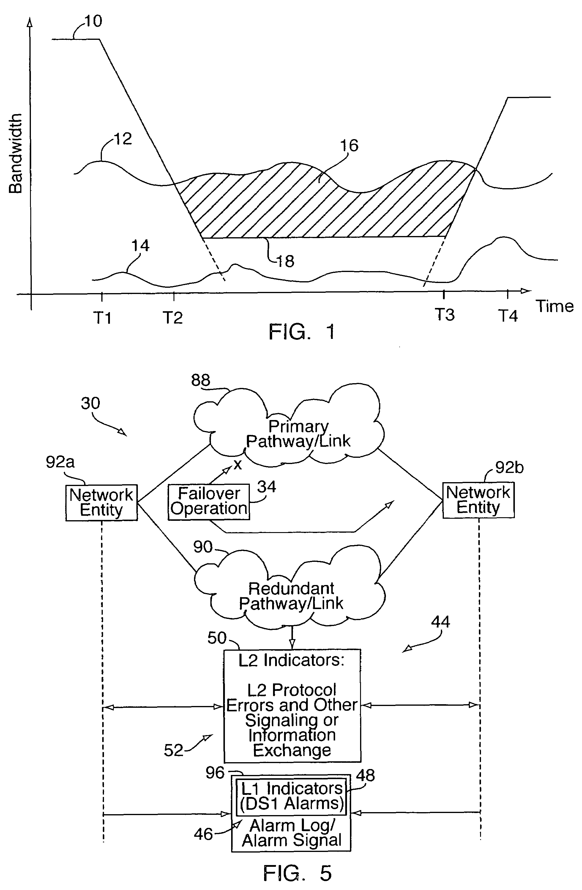
At time T1, an APS failure occurs, such as the failure of an optical backhaul circuit or the like.
Due to the time lag in detecting and switching from the failed component to the redundant component, there is a temporary decrease or interruption in the network resources for the multilink group, resulting in a concomitant reduction in effective bandwidth.
Because failover operations result in decreased bandwidth and a perceived congestion condition, and because the network normally handles congestion by dropping the load at the source, failover operations may result in dropped calls.
Delayed recoveries can lead to unnecessary traffic and / or call drops, which impact service conditions for both the end user and service provider.

Method used


Image

  • Method of maintaining traffic services through congestion caused by network failovers
  • Method of maintaining traffic services through congestion caused by network failovers
  • Method of maintaining traffic services through congestion caused by network failovers

Examples


Embodiment Construction

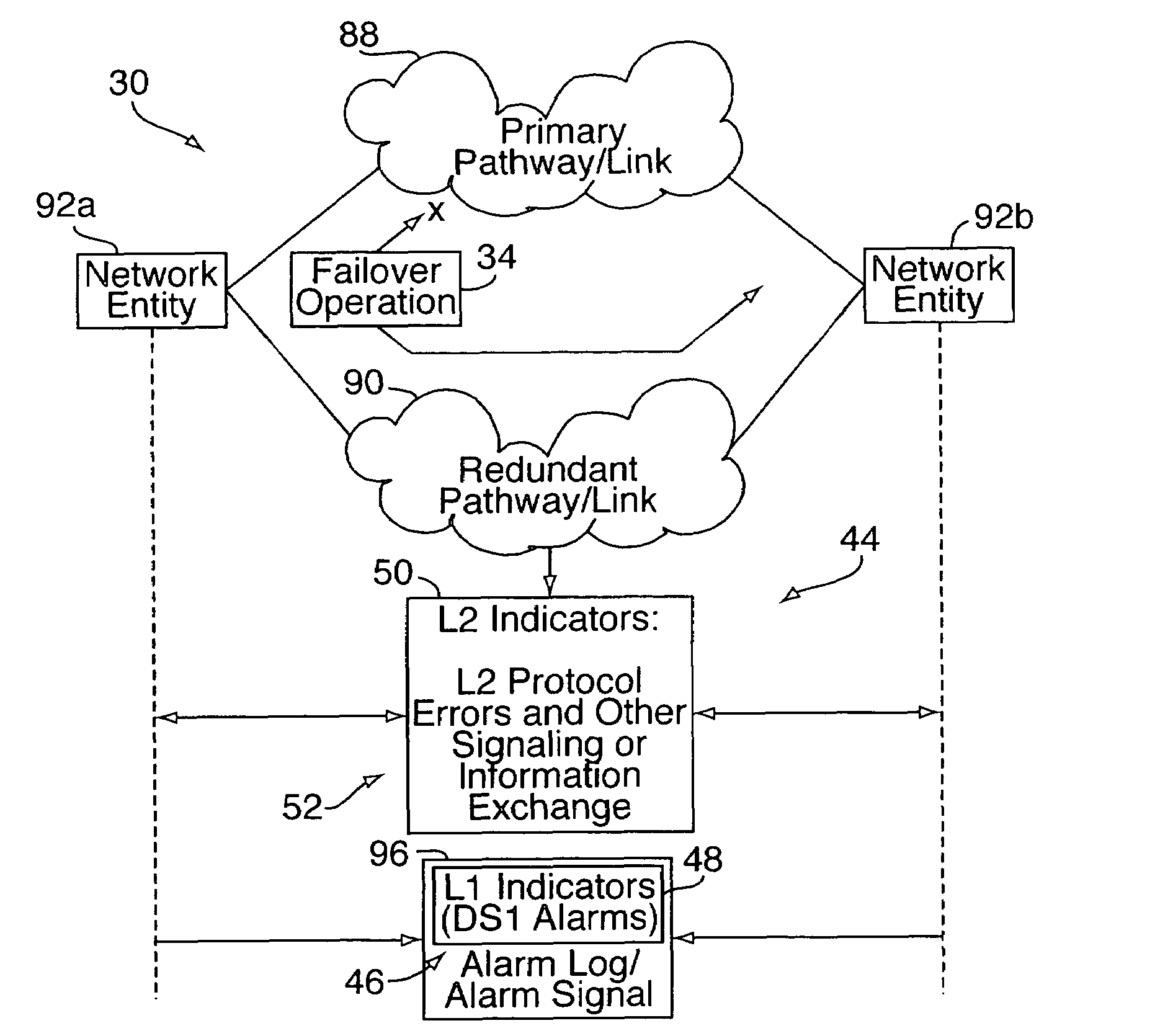
[0016]With reference to FIGS. 2-5, the present invention relates to a system and method 30 for controlling data traffic in a communication network 32, to maintain traffic services through congestion caused by network failovers 34. First and second hardware / software agents 36a, 36b are deployed to interface with one or more network entities 38. The first agent 36a monitors the L1 (physical) layer 40 of the network 32, and the second agent 36b monitors the L2 (data link) layer 42 of the network 32. The L1 and L2 layers 40, 42 are monitored for the presence of indicators 44 associated with failover operations 34 in the network 32. For example, one agent 36a may monitor the L1 layer 40 for DS1 alarms 46 or other L1 failover indicators 48. The second agent 36b may monitor the L2 layer 42 for L2 failover indicators 50 including protocol errors and / or information and signaling exchanges 52 associated with failover operations. (Generally speaking, the indicators 48, 50 are operational indic...


PUM


Abstract

In a method for controlling data traffic in a wireless or other communication network, one or more hardware / software agents are deployed to interface with one or more network entities such as routers, switches, backhaul transmission lines, and wireless base stations. The agents monitor the L1 (physical) and L2 (data link) layers of the network for the presence of indicators associated with network failover operations, such as DS1 alarms and protocol errors, respectively. Based on detected indicators across all monitored network entities, the agents determine if a failover operation has occurred. If so, data congestion associated with the failover operation is controlled according to a failover congestion monitoring and recovery mode (e.g., a data source backoff model), to reduce instances of dropped calls that would otherwise occur if the failover congestion were handled according to a general purpose congestion monitoring and recovery mode of the network.

Description

FIELD OF THE INVENTION[0001]The present invention relates to communication systems and, more particularly, to traffic control in a wireless telecommunication network or other network.BACKGROUND OF THE INVENTION[0002]In a communication network, “failover” is the capability to switch over automatically to a redundant or standby network component or communication link or pathway (e.g., computer server, router, controller, optical or other transmission line, or the like) upon the failure or abnormal termination of the previously active component or link. In operation, one or more designated network components are electronically monitored on an ongoing basis. Upon failure of one of the designated components, the system automatically carries out a failover operation for switching to a redundant or standby system, without the need for human intervention. Failover capability is usually provided in servers, systems, or networks where continuous availability and a high degree of reliability a...

Claims


Application Information

Patent Timeline
IPC IPC(8): G06F11/07
CPCG06F11/202H04L41/0896H04L41/0654
Inventor JAJOO, SANDESH R.SODANKOOR, CHANDRASHEKAR
Owner RPX CORP
Learn More