
Shape-Measuring Assembly for a Grinding Machine

a technology of grinding machine and assembly, which is applied in the direction of mechanical measuring arrangement, manufacturing tools, instruments, etc., can solve the problems of degrading the shape and quality of the roll surface, affecting the final shape of the finished roll, and affecting the final shap

Inactive Publication Date: 2008-07-10
HCC KPM LLC
View PDF9 Cites 8 Cited by
  • Summary
  • Abstract
  • Description
  • Claims
  • Application Information

AI Technical Summary

Benefits of technology

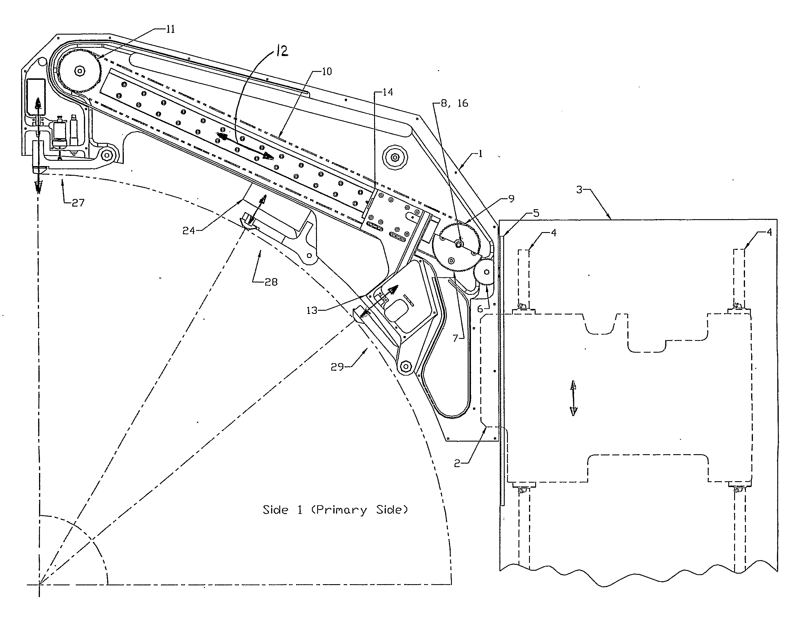
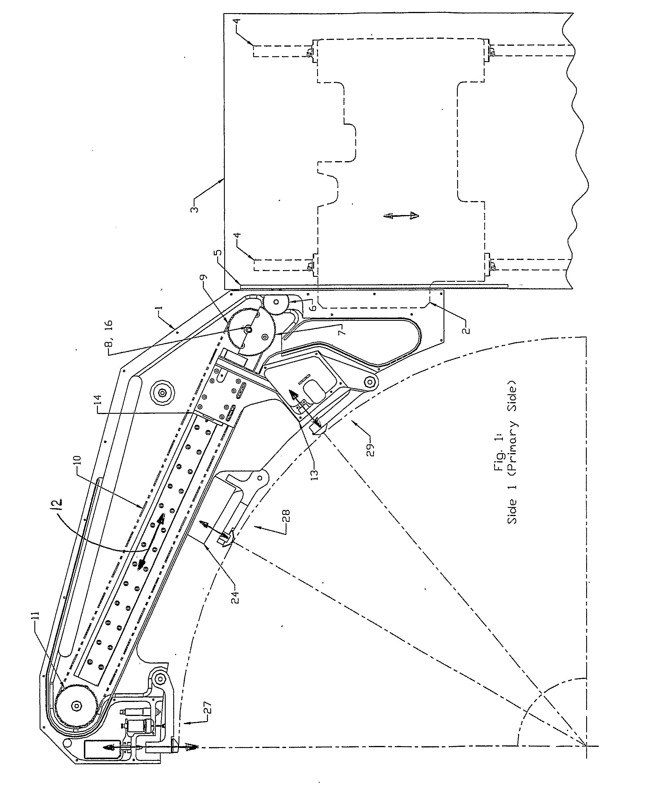
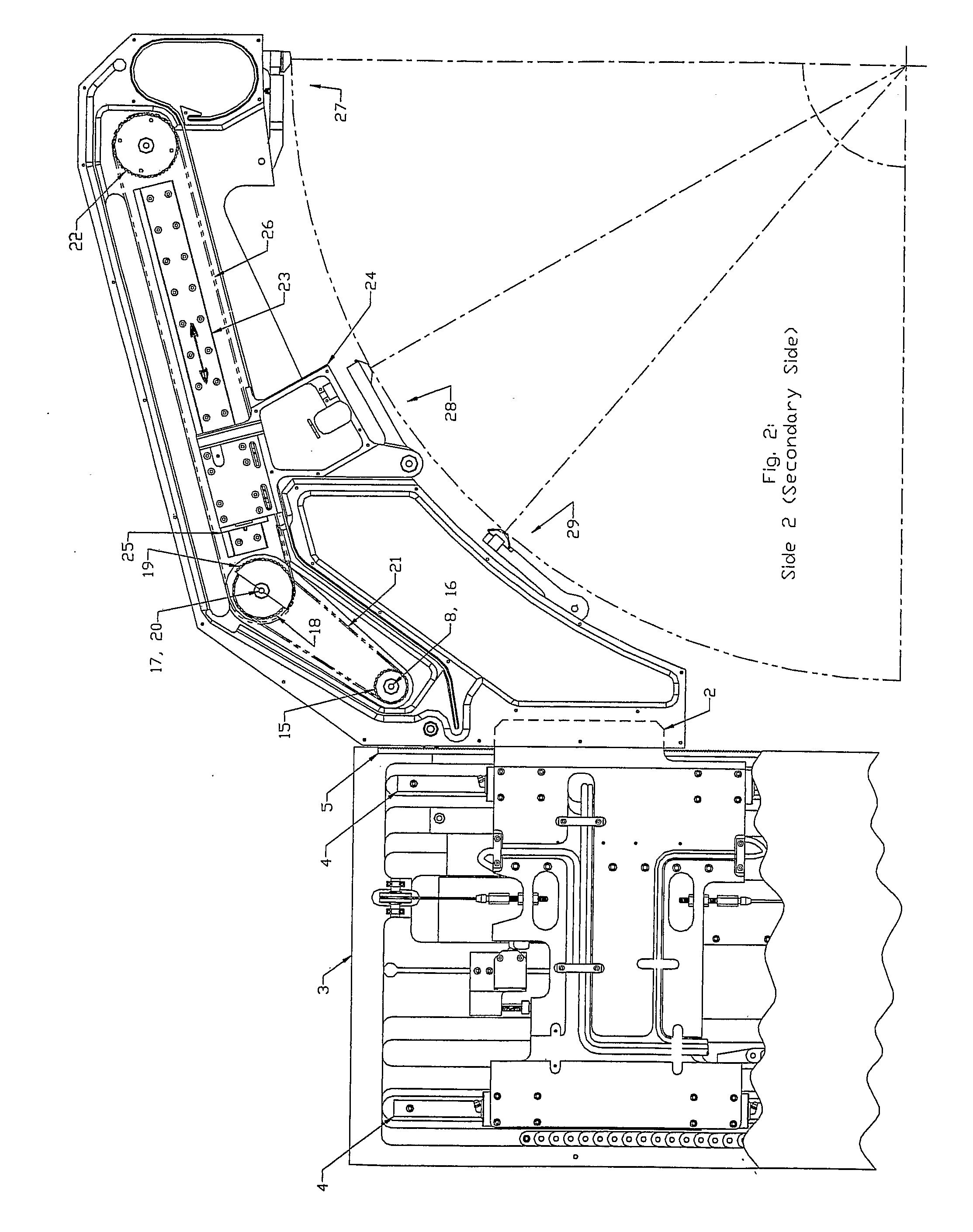
[0011]It is an advantage, according to the present invention, that the first fixed, first positionable and second positionable sensor probes can determine the position of three points on the surface of the roll, thus defining a circle on the surface of the roll including the location of the center of the circle and the diameter of the circle.
[0012]According to a preferred embodiment, a second arm is supported from a second arm carriage extending away from the frame. The second arm extends under the roll axis. A second fixed sensor probe is mounted near the distal end of the second arm for sensing the position of the surface of the roll. It is an advantage of this embodiment that at least three of the first fixed, second fixed, first positionable and second positionable sensor probes can determine the position of at least three points on the surface of the roll, thus defining a circle on the surface of the roll including the location of the center of the circle and the diameter of the circle.

Problems solved by technology

Use in the mill eventually leads to a degradation of shape and quality of the roll surface, at which point one must take the roll out of the mill for refinishing on a grinding machine.
A common problem with roll grinding stems from inaccuracies in the mechanical support of the roll which induce extraneous error movements of the roll as the roll turns.
Without compensation in the grinding process, these error movements may contribute to roundness or shape errors in the finished roll.
A two-point measurement cannot reliably distinguish roundness or shape errors from error movements of the roll.

Method used


Image

  • Shape-Measuring Assembly for a Grinding Machine
  • Shape-Measuring Assembly for a Grinding Machine
  • Shape-Measuring Assembly for a Grinding Machine

Examples


Embodiment Construction

[0022]The present invention comprises a shape-measuring assembly for a grinding machine for grinding a roll. The grinding machine includes a support to receive the roll so that the roll can turn around its longitudinal axis and a grinding wheel that can grind the surface around the circumference of the roll. An infeed mechanism brings the grinding wheel in contact with the roll and a traverse mechanism moves the grinding wheel parallel to the longitudinal axis between opposite ends of the roll.

[0023]A shape-measuring assembly or caliper assembly is configured to measure the shape of the roll and has mechanisms to place it in contact with the roll surface and to move it between opposite ends of the roll. The assembly includes a frame and a carriage supported by a linear guide connected to the frame. One or two measuring arms are connected to the linear guide in spaced relation. The linear guide is configured to enable each measuring arm to move relative to the frame and parallel to t...


PUM


Abstract

A linked transport mechanism and method that uses a single source of motive force to synchronously position multiple displaceable sensors of a shape-measuring assembly onto a roll received in a roll grinding machine. At least two sensors (28, 29) are mounted on linear slides on at least one measuring arm (1). The complete shape-measuring assembly includes at least three sensors (27, 28, 29) or measuring points to allow the calculation of the cross-sectional shape of the roll and the extraneous error movement of the roll. At least one measuring arm is connected to a linear guide (4) of the frame (3). The linear motor is connected between the frame and the measuring arms. The linked transport mechanism assures the synchronous accurate positioning of the sensors, each at a fixed angle through the roll center, over the entire range of roll diameters that the grinding machine may receive.

Description

BACKGROUND OF THE INVENTION[0001]1. Field of the Invention[0002]This invention relates generally to the field of roll or cylinder grinding machines and, more particularly, to a measuring assembly or caliper assembly utilized to measure the geometry or configuration of rolls or cylinders received on grinding machines.[0003]2. Description of Related Art[0004]Rolling mills in the steel, aluminum and paper industries commonly use metal rolls in shaping products, such as a piece or sheet of metal, aluminum foil, or sheet of paper. The rolls may have a surface cover of a material other than metal, such as rubber, polyurethane or ceramic. Use in the mill eventually leads to a degradation of shape and quality of the roll surface, at which point one must take the roll out of the mill for refinishing on a grinding machine. U.S. Pat. No. 4,811,524 to Corallo describes a grinding machine.[0005]U.S. Pat. No. 6,159,074 to Kube et al. describes a caliper assembly for a grinding machine. This calip...

Claims


Application Information

Patent Timeline
IPC IPC(8): G01B5/08G01B3/14G01B5/20
CPCB24B5/37B24B49/045G01B5/207G01B5/08G01B5/201G01B3/14
Inventor KUBE, SAMUEL C.PLEKKER, ALBERT A.
Owner HCC KPM LLC
Learn More