Methods and systems for fracturing subterranean wells

a technology of hydraulic fracturing and subterranean wells, applied in the direction of fluid removal, survey, borehole/well accessories, etc., can solve the problems of process sometimes being stopped, damage surface equipment or the well casing itself, and the pressure of the pumping system exceeding the design limits of the system, so as to reduce the risk of undesired results and increase the cost of providing expert labor

Active Publication Date: 2008-07-10
HALLIBURTON ENERGY SERVICES INC
View PDF6 Cites 80 Cited by
  • Summary
  • Abstract
  • Description
  • Claims
  • Application Information

AI Technical Summary

Benefits of technology

[0011]Thus, successful fracturing includes achieving desired fracture dimensions and a desired proppant distribution within the fracture. Because of the complexity of achieving both of these simultaneously, there is a need for real-time control of both fracture formation and proppant placement during a fracturing process to achieve total desired re

Problems solved by technology

Too high a concentration of proppant can lead to an undesirable and premature “screen-out” in which the solids concentration within the fracture becomes so high that the pumping pressure exceeds the design limits of the system.
The process must sometimes be stopped because in many situations, continuing pumping will damage surface equipment or the well casing itself, e.g. rupturing the well casing.
In other situations, the proppant might collect at an obstruction or within a too-narrow of a fracture, resulting in screen-out as well.
Another common problem for a fracturing process is that the current resulting fracture is of the wrong geometry, orientation, directional positioning, and/or dimensions, or tending to be of the wrong geometry, orientation, directional positioning, or dimensions.
This type of problem can be related to the inconsistency of subterranean geologic formations s

Method used


Image

  • Methods and systems for fracturing subterranean wells
  • Methods and systems for fracturing subterranean wells
  • Methods and systems for fracturing subterranean wells

Examples


Embodiment Construction

[0029]The numerous innovative teachings of the present application will be described with particular reference to the presently preferred embodiment (by way of example, and not of limitation).

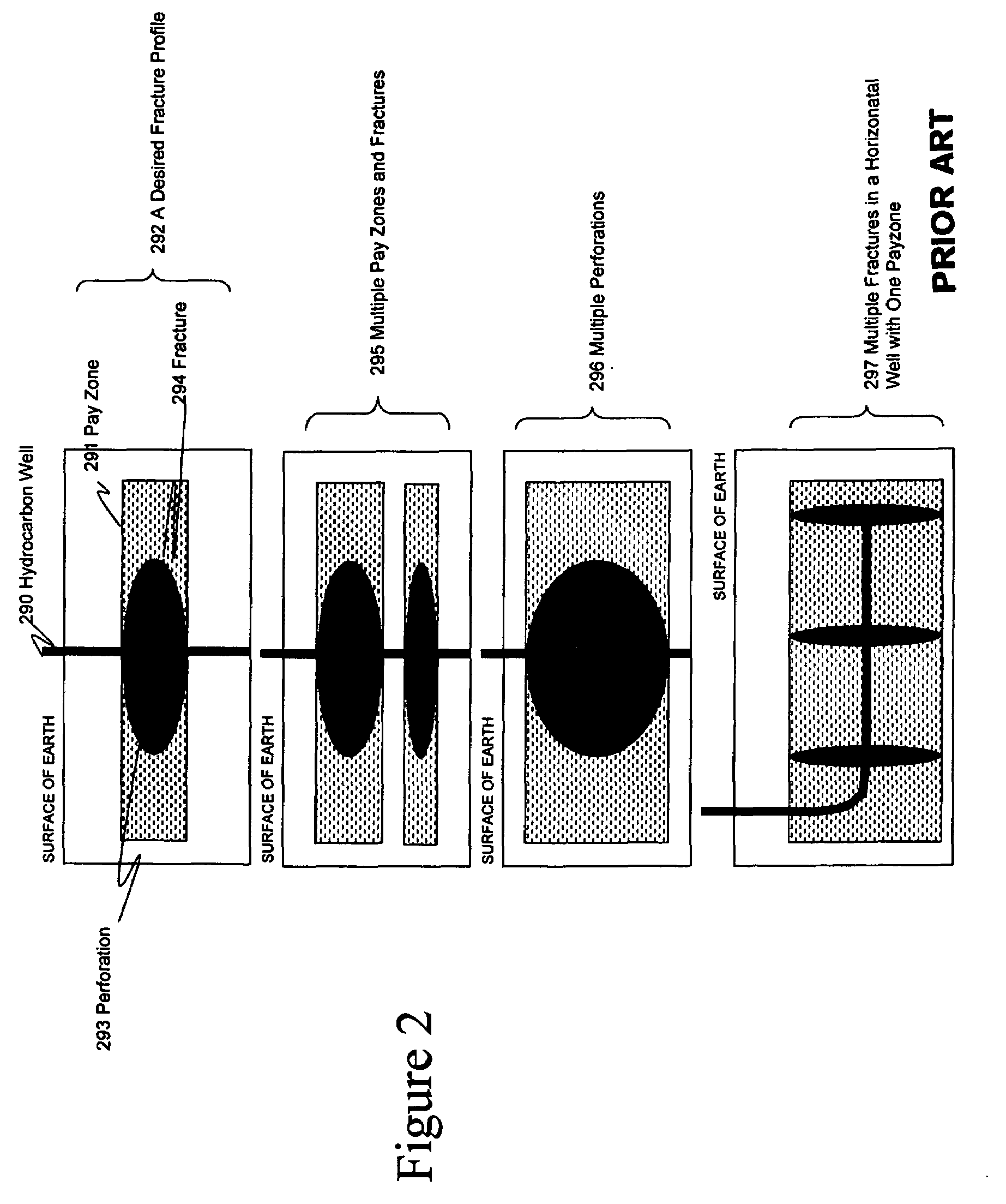
[0030]FIG. 2 shows four embodiments of desired side-view profiles of resulting subterranean fractures, such as can be formed using the methods and systems of the present innovations, by way of examples, and not of limitations. In one embodiment, desired fracture profile 292 shows a side view of a subterranean fracture 294 emanating from perforation 293 in hydrocarbon well 290 that is perfectly contained vertically within pay zone (e.g. hydrocarbon-bearing formation or zone) 291. Any extension beyond the pay zone can be undesirable because no extra hydrocarbon-drainage area is opened-up for production and the fracturing time and fluid was wasted in achieving the non-paying fracture portion. In another embodiment, multiple horizontal pay zones or fractures 295 can be accessed and formed from the ...


PUM


Abstract

New methods and systems for subterranean fracturing for hydrocarbon wells. A plan of the fracture propagation and in-fracture proppant distribution is used with a real-time model of the status of the fracture dimensions and in-fracture proppant concentration to automatically control flow rates and properties of a fracturing fluid flow stream being used to induce and prop the fracture. Real-time measurements of the status of the fracture are made using surface and/or down-hole sensors. Real-time control over the flow rate and properties of a fracturing fluid flow stream are made by manipulating the fracturing fluid supply equipment. Real-time modifications of the fracturing model are made by comparing fracture sensor measurements of actual fracture dimensions to the predicted dimensions, and then adjusting the model for inaccuracies. Real-time updates to the fracturing plan are made by comparing actual fracture and propping results to desired results, and then adjusting to achieve optimal results.

Description

BACKGROUND AND SUMMARY OF THE INVENTION[0001]The present application relates to methods and systems for conducting the hydraulic fracturing of subterranean wells, and more particularly to the control of processes related to subterranean hydraulic fracturing used to stimulate the production of hydrocarbon wells, and most especially to real-time and automatic control of fracture propagation and placement of proppant therein.[0002]The following paragraphs contain some discussion, which is illuminated by the innovations disclosed in this application, and any discussion of actual or proposed or possible approaches in these paragraphs does not imply that those approaches are prior art.Background: Hydrocarbon Formation Fracturing and Propping[0003]Subterranean hydraulic fracturing is conducted to increase or “stimulate” production from a hydrocarbon well. To conduct a fracturing process, high pressure is used to pump special fracturing fluids, including some that contain propping agents (“...

Claims


Application Information

Patent Timeline
IPC IPC(8): E21B43/26
CPCE21B43/267
Inventor DYKSTRA, JASON D.
Owner HALLIBURTON ENERGY SERVICES INC
Why Eureka
Try Eureka