Device for dispensing plastic fasteners

a technology for fasteners and devices, applied in the field of plastic fasteners, can solve the problems of unnecessarily slow stroke speed, time-consuming and laborious process, and inconvenient dispensing of fasteners of the type described above, and achieve the effect of maximizing productivity and energy-saving

Active Publication Date: 2008-07-10
AVERY DENNISON CORP
View PDF14 Cites 12 Cited by
  • Summary
  • Abstract
  • Description
  • Claims
  • Application Information

AI Technical Summary

Benefits of technology

[0019]It is still another object of the present invention to provide a device as described above which is energy efficient yet designed to maximize productivity.
[0020]It i

Problems solved by technology

Although well known in the art, it has been found that fastener dispensing devices of the type described above suffer from some notable shortcomings.
Due to the inherent limitations associated with a single stroke machine, the plurality of fasteners can only be dispensed by repeatedly actuating the machine, which is a time-consuming and labor intensive process.
However, this stroke speed has been found to be unnecessarily slow when the device is used to dispense plastic fasteners through relatively thin materials.
As a result, the productivity that is achieved using such a machine is limited.
As a third shortcoming, fastener di

Method used


Image

  • Device for dispensing plastic fasteners
  • Device for dispensing plastic fasteners
  • Device for dispensing plastic fasteners

Examples


Embodiment Construction

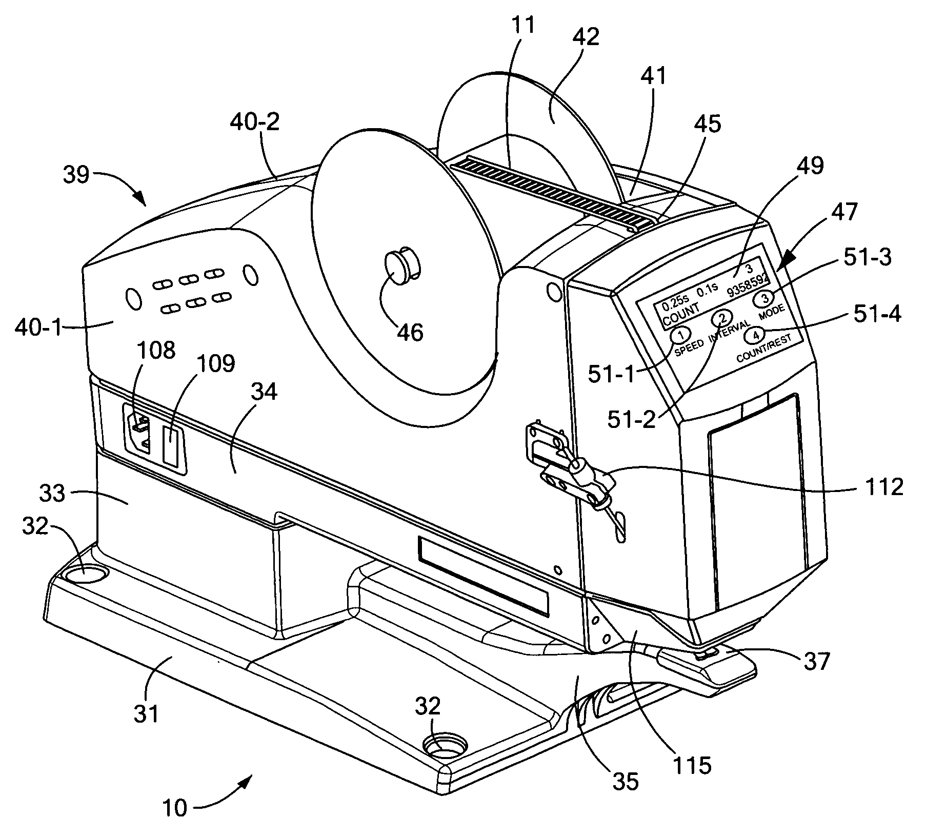
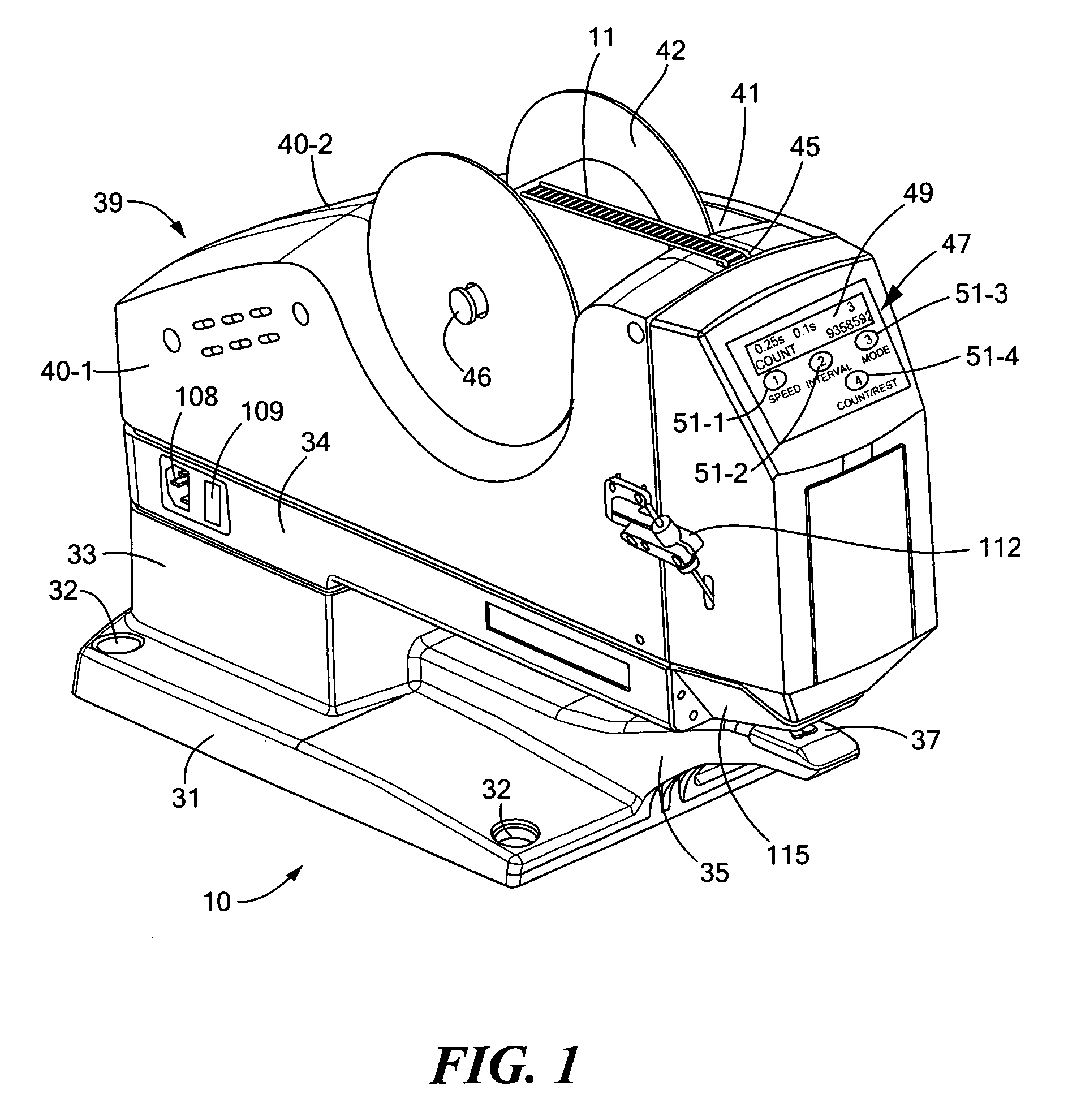
[0044]Referring now to FIG. 1, there is shown a device for dispensing individual plastic fasteners from a supply of continuously connected ladder stock, said device being constructed according to the teachings of the present invention and identified generally by reference numeral 10. As can be appreciated, device 10 can be used in an automated packaging line, for example, to secure together two or more products, such as socks, gloves, towels or other similar items, using one or more plastic fasteners from ladder stock. For simplicity and clarity, parts not directly pertaining to the invention are only diagrammatically shown in the drawings and are not described in detail below.

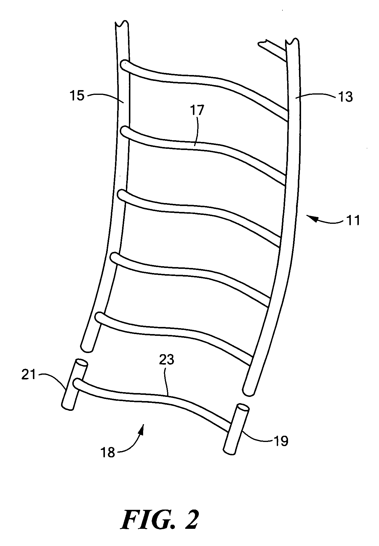
Continuous Supply of Ladder Stock 11

[0045]As noted above, device 10 is designed to dispense individual plastic fasteners from various types of continuously connected ladder stock. For example, the supply of ladder stock (also referred to herein as fastener stock) may be of the type described in U.S. Pat. No. 4...


PUM


Abstract

A device for dispensing individual plastic fasteners from a continuous supply of 0.1875 inch pitch ladder stock includes a head assembly that is designed to receive the supply of ladder stock, sever an individual fastener from the supply ladder stock and eject the individual fastener during a single stroke of its actuation cycle. The device also includes a stepper motor for driving the head assembly through its actuation cycle, a DC power switching supply for regulating the power supplied to the stepper motor from an AC input power source, and a controller for collecting historical data relating to usage of the device and for regulating operation of the stepper motor. The controller is programmed to enable certain operational characteristics, such as stroke speed and mode, to be regulated through a user interface which includes a screen display and a plurality of control buttons.

Description

CROSS-REFERENCE TO RELATED APPLICATIONS[0001]The present application is a continuation-in-part of presently-pending U.S. patent application Ser. No. 11 / 593,452, filed Nov. 6, 2006, the disclosure of which is incorporated herein by reference.BACKGROUND OF THE INVENTION[0002]The present invention relates generally to plastic fasteners and more particularly to devices used in the dispensing of plastic fasteners.[0003]In U.S. Pat. No. 4,039,078 to A. R. Bone, which is incorporated herein by reference, there are disclosed several different types of plastic fasteners (also commonly referred to in the art as plastic attachments). Each plastic fastener described in the patent is manufactured in an H-shaped configuration, with two shortened parallel cross-bars, or T-bars, being interconnected at their approximate midpoints by a thin, flexible filament which extends orthogonally therebetween. Each type of plastic fastener represented in the patent is shown as being fabricated as part of conti...

Claims


Application Information

Patent Timeline
IPC IPC(8): B65G47/14
CPCB65C7/00Y10T24/10G09F3/12
Inventor COOPER, WILLIAM J.EARLEY, JOHNRAYMOND, JEFFREY A.LIU, SHAOMING
Owner AVERY DENNISON CORP
Why Eureka
Try Eureka