Image display apparatus with ambient light sensing system

a technology of ambient light and display apparatus, which is applied in the direction of identification means, sustainable manufacturing/processing, instruments, etc., can solve the problems of not solving a realistic problem, high-accuracy detection and control cannot be obtained, etc., and achieve the mechanical reliability of packaging, the effect of maintaining product yield and packaging cos

Inactive Publication Date: 2008-07-10
JAPAN DISPLAY INC
View PDF9 Cites 13 Cited by
  • Summary
  • Abstract
  • Description
  • Claims
  • Application Information

AI Technical Summary

Benefits of technology

[0015]In the process for forming the pixel region of the image display apparatus (and driver part), a signal processing circuit for generating a control signal corresponding to the photo-sensor and the illuminance, and the packaging cost, mechanical reliability caused by packaging, and product yield can be maintained.

Problems solved by technology

As a result, highly accurate detection and control cannot be obtained (for instance, a wavelength band following the visual sensitivity and the absorption intensity distribution cannot be replicated by using one kind of sensor).
However, it is not one which solves a realistic problem where the difficulty of packaging into an image display apparatus is solved.

Method used


Image

  • Image display apparatus with ambient light sensing system
  • Image display apparatus with ambient light sensing system
  • Image display apparatus with ambient light sensing system

Examples


first embodiment

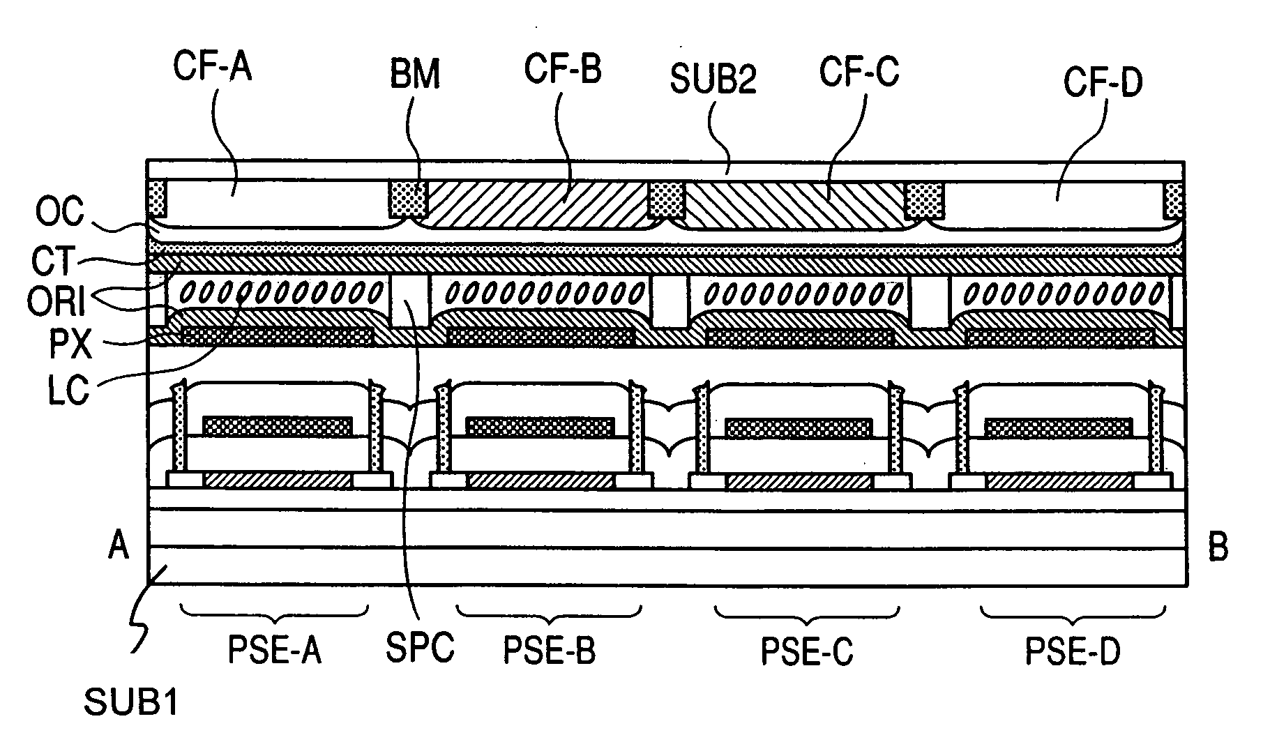
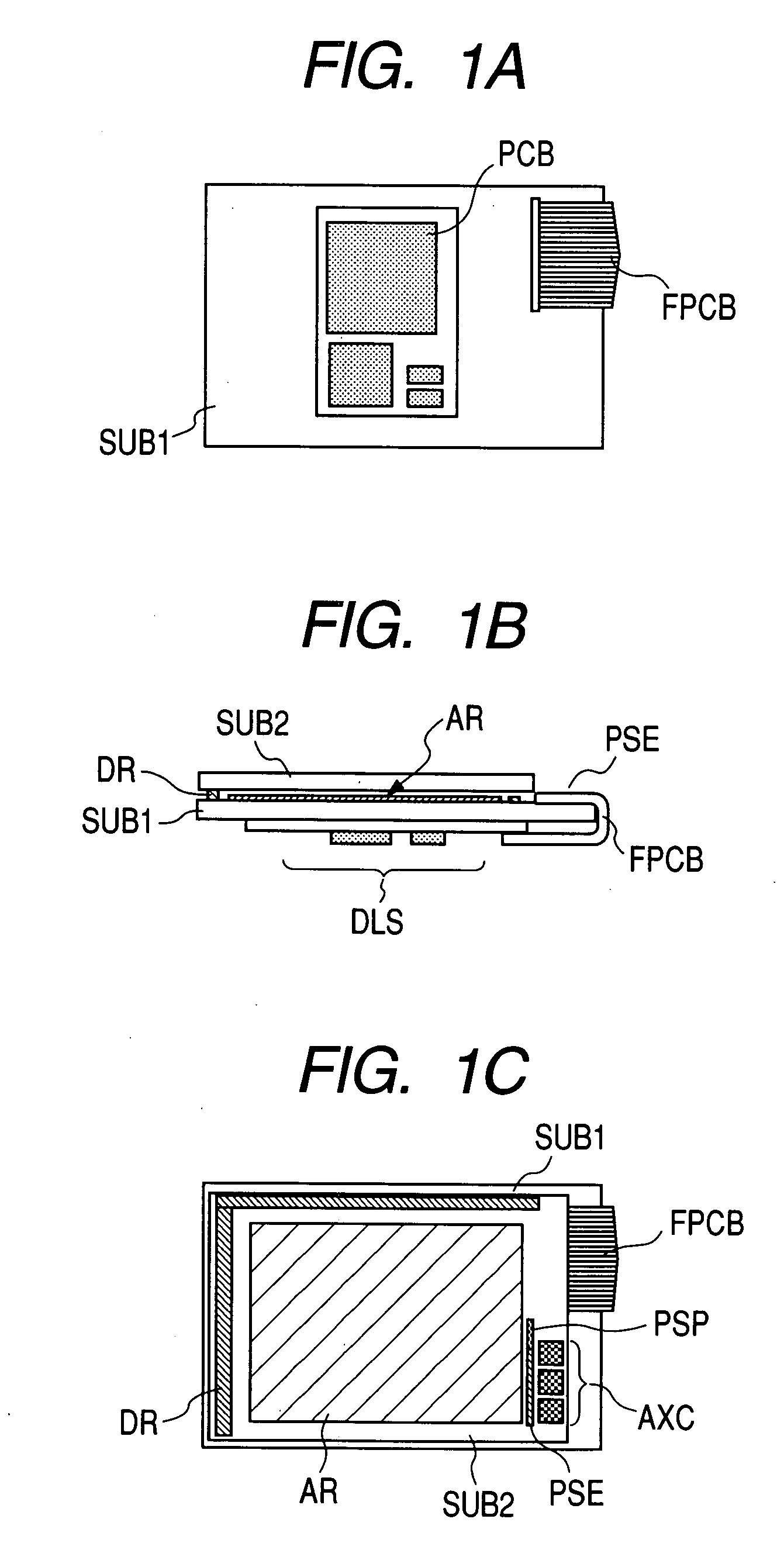
[0049]FIG. 1 is a drawing illustrating an example of a display panel of the present invention where an ambient light sensing system is built-in. FIG. 1A is a rear elevation of a panel, FIG. 1B is a bottom view of a panel, and FIG. 1C is a front view of a panel, the same as FIGS. 10A to 10C. The panel includes a first substrate SUB 1 and a second substrate SUB 2. Codes which are the same as FIGS. 10A to 10C correspond to parts having the same functions. Like FIGS. 10A to 10C, a backlight is not shown in the figure.

[0050]In the liquid crystal panel of the embodiment 1 where an ambient light sensing system is built-in, plural photo-sensors PSE, a signal processing circuit PSP, and a signal processing circuit AXC for generating a signal which controls the brightness of the pixel are formed simultaneously over the same substrate (first substrate SUB 1) in a pixel formation process. The output of the signal processing circuit PSP and the input of the control signal system, etc. are connec...

second embodiment

[0077]The second embodiment is one where an image display apparatus of the present invention is applied to an organic EL display apparatus. A panel constituting the organic EL display apparatus has the same configuration, up to the thin-film-transistor, in the first substrate of the liquid crystal panel which consists of a liquid crystal display apparatus explained in the first embodiment. In the organic EL panel, it is assumed that a pixel electrode driven by the electrode (source-drain) of the thin-film-transistor is one electrode, an organic EL light-emitting layer is coated over this one electrode, and another electrode is deposited covering plural pixels. Then, the second substrate is used as a sealing board covering another electrode. One electrode of plural photo-sensors is not coated with the organic EL light-emitting layer.

[0078]In the second embodiment, plural photo-sensors are provided over the main face of the first substrate, the same as the first embodiment, and the de...


PUM

PropertyMeasurementUnit
wavelengthaaaaaaaaaa
thickaaaaaaaaaa
thickaaaaaaaaaa

Abstract

An image display apparatus with an illuminance sensor, where the packaging cost, mechanical reliability due to packaging, and product yield are maintained. In the same semiconductor film as a thin-film-transistor (TFT) consisting of a pixel formed over an insulating substrate constituting a pixel, plural photo-sensors composed of a TFT for detecting light which has different detecting wavelength bands, and a signal processing circuit for generating a signal which controls the brightness of the pixel on the basis of the output of the photo-sensor are formed. The photo-sensor detects light energy of different wavelength bands by using a filter having a different film thickness of the semiconductor film or a different light transmission band. Ambient illuminance is detected by processing the output of each sensor in the signal processing circuit. The detected signal is fed back to the brightness control of the pixel.

Description

CLAIM OF PRIORITY[0001]The present application claims priority from Japanese application JP 2007-001117 filed on Jan. 9, 2007, the content of which is hereby incorporated by reference into this application.FIELD OF THE INVENTION[0002]The present invention relates to an image display apparatus which has an ambient light sensing system where the brightness of a display image is controlled corresponding to the illuminance of the surroundings by using a photo-sensor generating a control signal corresponding to the illuminance of the surroundings.BACKGROUND OF THE INVENTION[0003]A so-called display with an ambient light sensing system is known, where the brightness of a display image of an image display apparatus (hereinafter, it is also called a display) is controlled corresponding to the ambient light of the surroundings. A basic configuration of this kind of display generally has one detecting element (photo-sensor) for detecting ambient light (light around the display), a signal proc...

Claims


Application Information

Patent Timeline
Patent Type & Authority Applications(United States)
IPC IPC(8): H01L33/00G02F1/133G09F9/00G09F9/30G09G3/20G09G3/30G09G3/34G09G3/36H01L27/32H01L51/50
CPCG02F1/13318G09G3/3406G09G2320/0666G09G2360/145H01L27/1446Y02E10/546H01L31/03682H01L31/03762H01L31/143H01L31/182H01L31/202H01L31/02162Y02P70/50
Inventor TAI, MITSUHARUKAGEYAMA, HIROSHI
Owner JAPAN DISPLAY INC
Why Eureka
Try Eureka