Remote Operation Apparatus and Service Center

a technology of remote operation and service center, which is applied in the direction of instruments, anti-theft devices, testing/monitoring control systems, etc., can solve the problems of increasing the cost due, difficulty in accurately measuring the arrival time, and delay

Inactive Publication Date: 2008-07-10
TOYOTA JIDOSHA KK
View PDF14 Cites 28 Cited by
  • Summary
  • Abstract
  • Description
  • Claims
  • Application Information

AI Technical Summary

Benefits of technology

[0011]It is a general object of the present invention to provide an improved and u

Problems solved by technology

If it takes a long time from an operation of the portable terminal until the in-vehicle equipment is actually operated, there may be a case where a condition surrounding the vehicle is changed, which causes an unexpected problem.
Thus, it is difficult to accurately measure an arrival time since a radio propagation distance is short.
Additionally, even if the measurement is possible, it is required to synchronize a clock of the portable terminal with a clock of the vehicle, thereby increasing a cost due to necessity of a system for acquiring synchronization.
When performing a remote operation through a service center, depending on a location of a vehicle, an operation signal may not reach the vehicle

Method used


Image

  • Remote Operation Apparatus and Service Center
  • Remote Operation Apparatus and Service Center
  • Remote Operation Apparatus and Service Center

Examples


first embodiment 1

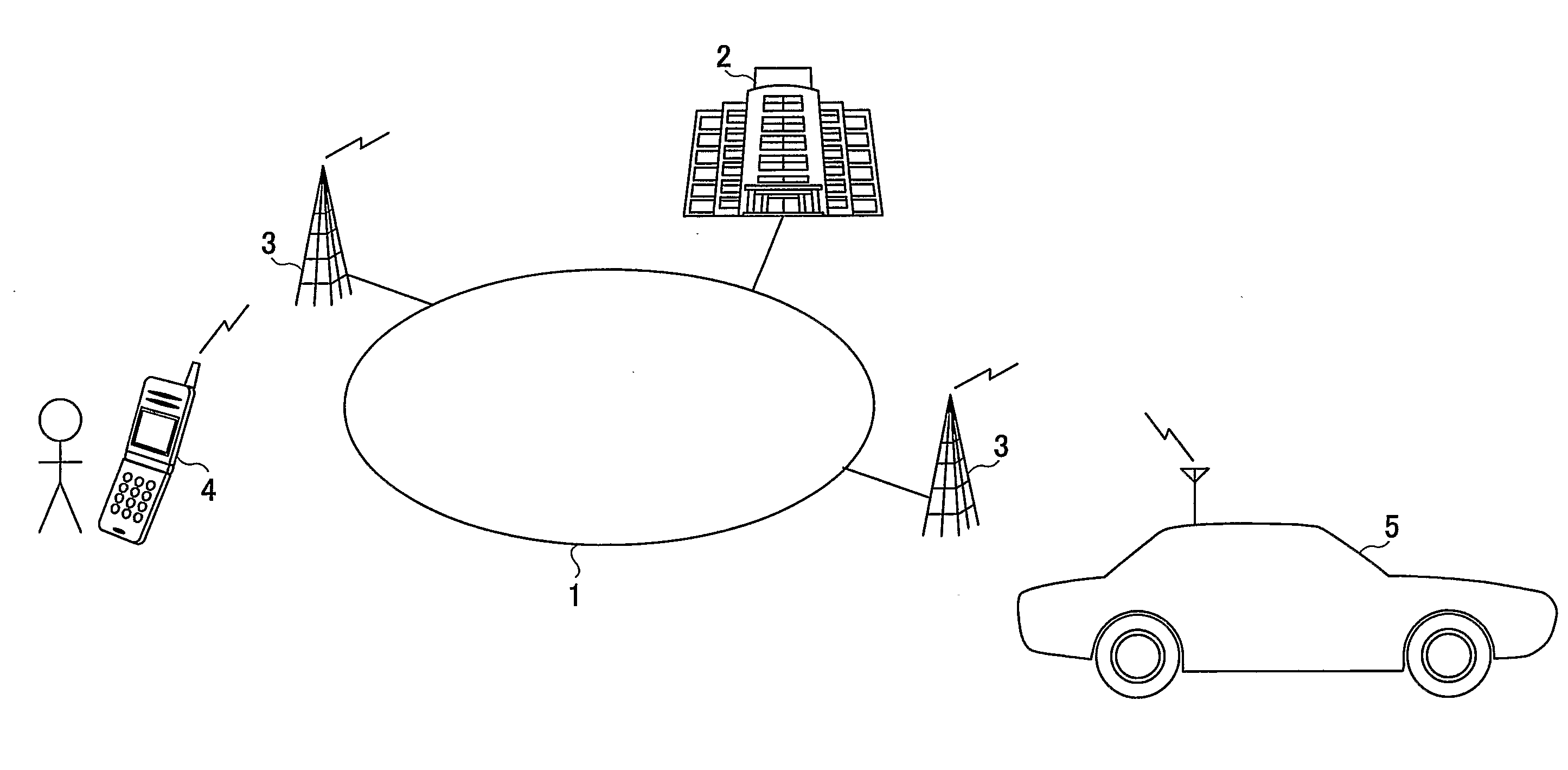
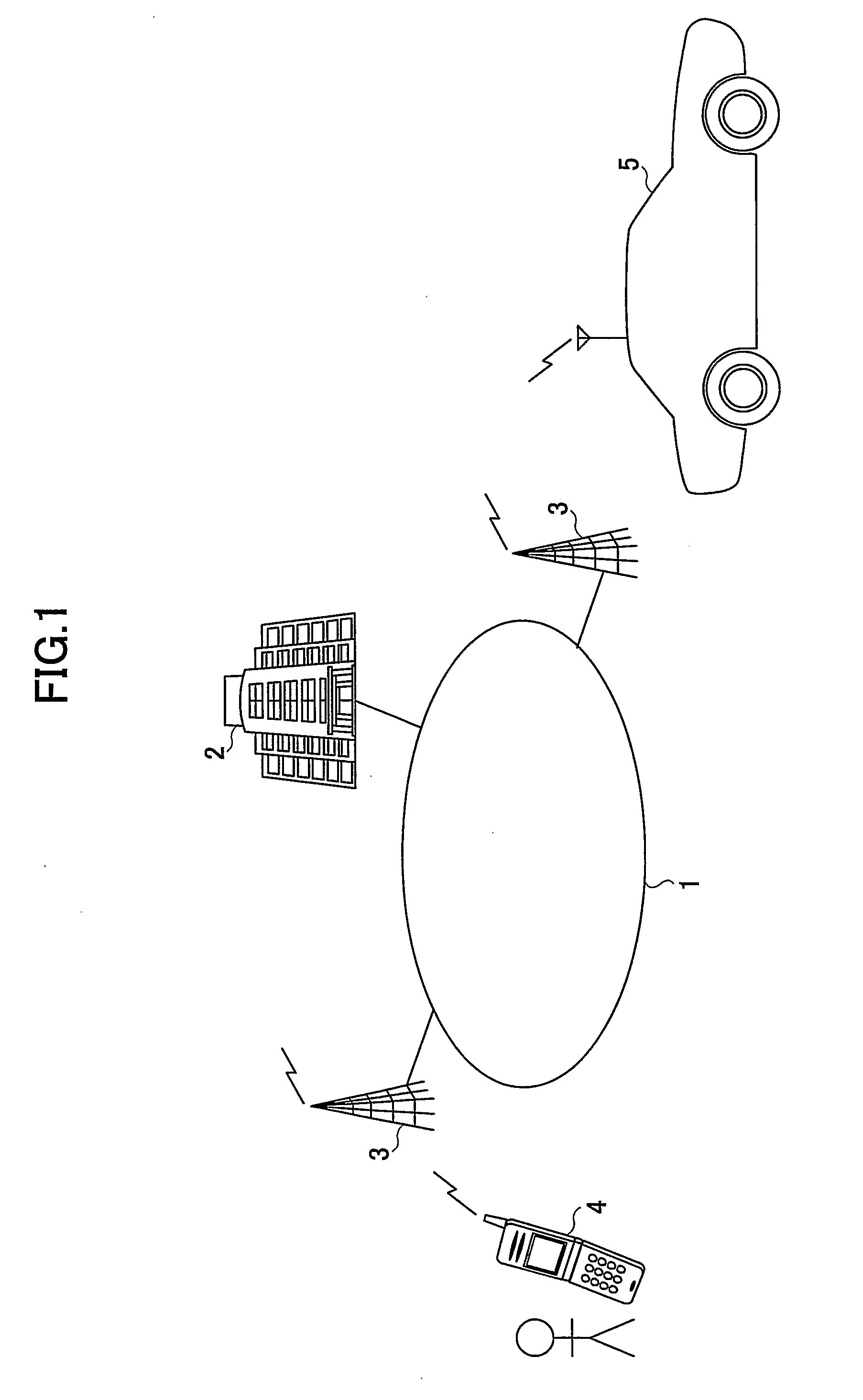
[0028]FIG. 1 is an illustration of an entire remote operation system in which an operation signal is transmitted from a portable terminal 4, which is carried by a user, to a vehicle 5 through a service center 2 and the vehicle 5 controls an in-vehicle device in accordance with the operation signal.

[0029]The remote operation system (or a remote control system) comprises the service center 2 managing operation states of a plurality of equipments mounted on the vehicle 5, the vehicle 5 remote-operated by a user, and the portable terminal 4 carried by the user. The service center 2 is connected to a network 1 such as the Internet or the like. The vehicle 5 and the portable terminal 4 are communicable with base stations 3 connected to the network 1. It should be noted that the user is a person using the remote operation system, which is registered in the service center 2 and capable of operating the vehicle 5 through the portable terminal 4, that is, for example, the user is a driver of ...

second embodiment

[0069]The remote operation system, in which the concept of timeout is introduced and the in-vehicle device of the vehicle 5 is not operated, was explained in the first embodiment, and setting of the timeout period will be explained in the second embodiment.

[0070]Since a user cannot visually check the vehicle 5 when the user performs a remote operation, the user wants to check whether or not the control according to the user's operation was performed on the in-vehicle device as soon as possible. Thus, in the remote operation system, it is preferable to notify the user of an occurrence of timeout. However, if the timeout period is set to a short time, a number of remote operations that runs out of time may be increased, which is not preferable. Thus, it is preferable that the timeout period is set so that a large part of the remote operations do not run out of time but a determination of timeout is made when there is a high possibility that a long time is taken until a notification is...


PUM


Abstract

A remote operation apparatus controls a vehicle based on an operation signal transmitted from a portable terminal of a user through a service center. A time comparing part compares a first reception time, at which the service center receives the operation signal from the portable terminal, with an operation time at which the user performs a remote operation. A discarding part discards the operation signal when a difference between the reception time and the operation time, as a result of a comparison by the time comparing part, is equal to or longer than a predetermined time period.

Description

TECHNICAL FIELD[0001]The present invention relates remote control techniques of in-vehicle equipments and, more particularly, to a remote operation apparatus (or a remote control apparatus) for operating an in-vehicle equipment in accordance with an operation performed at a remote place and a service center for mediating transmission of an operation performed at a remote place to an in-vehicle equipment.BACKGROUND ART[0002]There is suggested a remote control technique for operating an in-vehicle equipment by a portable terminal, which is carried by a driver, through a service center. Using such a remote control technique, it is possible to control an operation of an in-vehicle equipment from a remote place, such as locking or unlocking a vehicle door and opening or closing a vehicle window, controlling a vehicle security function, starting an engine, or the like (for example, refer to Patent Document 1).[0003]In a case of a remote operation, an arrival time of an operation signal tr...

Claims


Application Information

Patent Timeline
IPC IPC(8): G05B23/02
CPCB60R25/102B60R25/1004
Inventor TAKI, NAOKIWATANABE, ATSUSHIITO, HIDEKAZU
Owner TOYOTA JIDOSHA KK
Why Eureka
Try Eureka