Lighting Unit and Display Equipment Provided Therewith
- Summary
- Abstract
- Description
- Claims
- Application Information
AI Technical Summary
Benefits of technology
Problems solved by technology
Method used
Image
Examples
embodiment 1
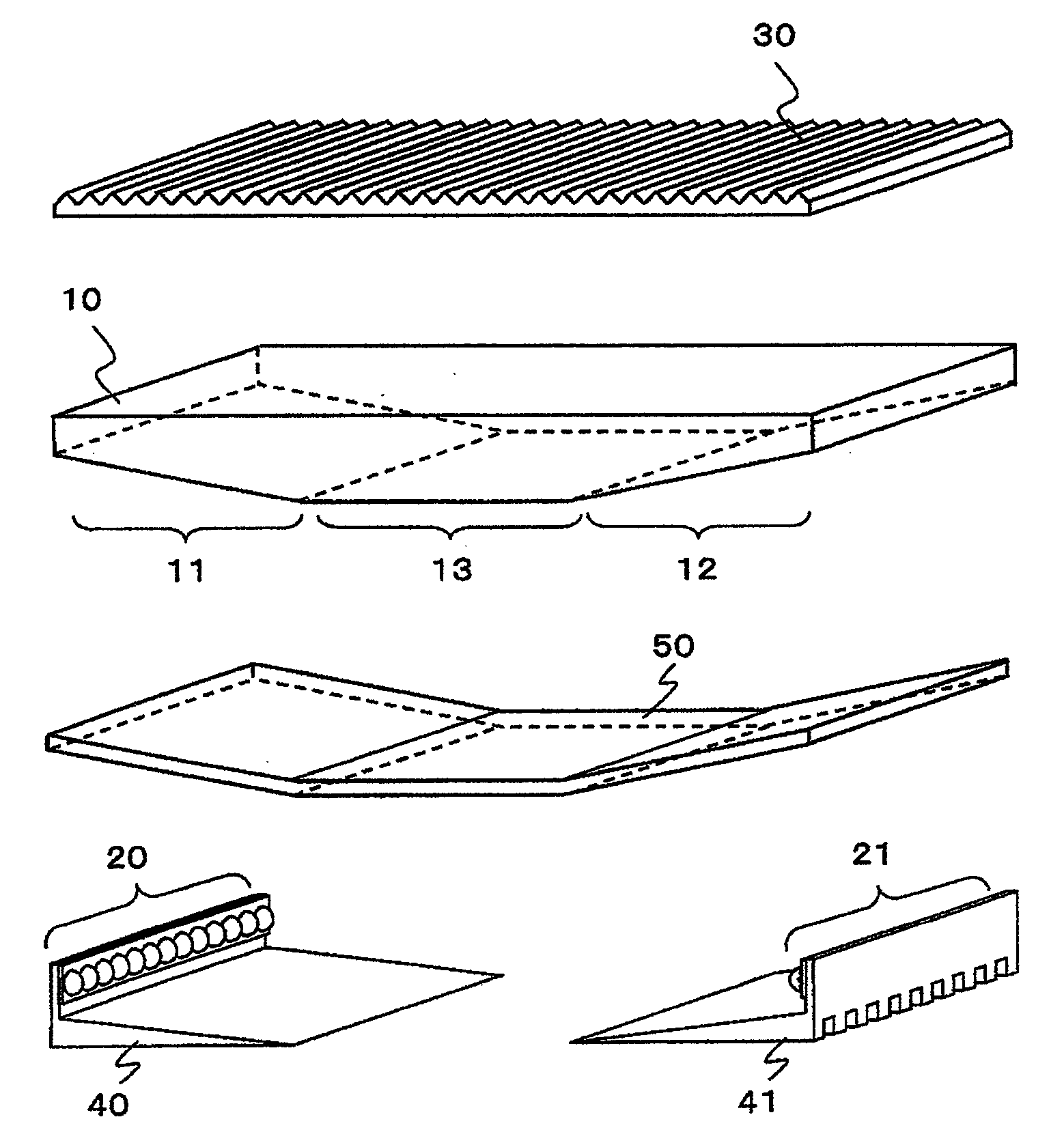
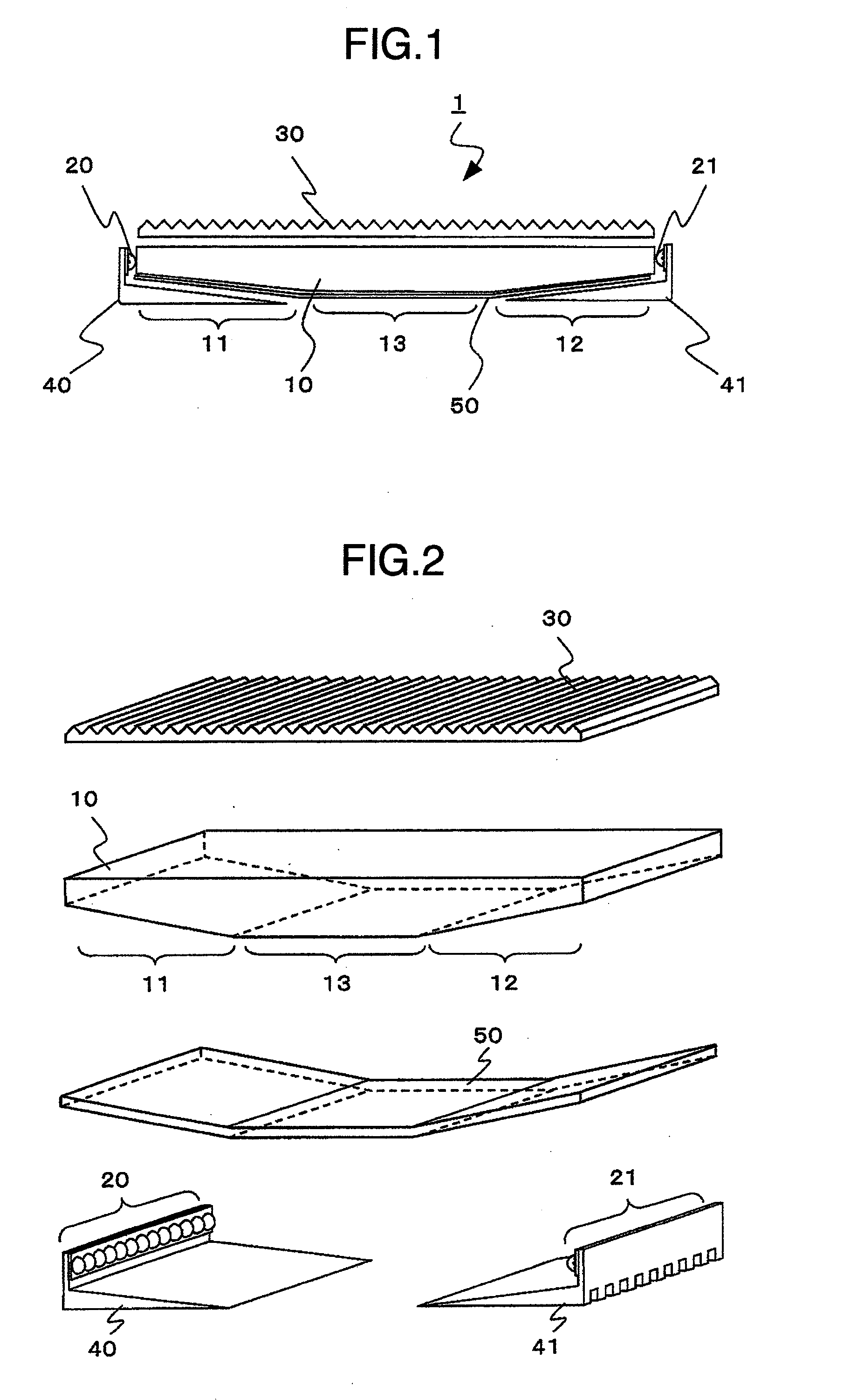
[0031]FIG. 1 shows an example of a lighting unit according to the present invention and is a partial cross section showing a schematic configuration of a main part. And, FIG. 2 is a schematic cross-eyed diagram showing the configuration of the main part of the lighting unit according to the present invention.
[0032]In FIGS. 1 and 2, a lighting unit 1 is arranged on the rear of a display panel not shown which displays the image by adjusting the transmitted light intensity of the light and it is appropriate for the lighting unit which illuminates the display panel from the rear. For the display panel, a display panel which displays the image by adjusting the transmitted light intensity of the light which enters can be used, and in particular, a liquid crystal display panel which has a long lifetime and can conducts a matrix display can be used.
[0033]The lighting unit 1 is configured with a light-guiding member 10, a first light source group 20 and a second light source group 21 which a...
embodiment 2
[0084]Next, it will be explained about the other embodiment of the light-guiding member in the lighting unit according to the present invention. FIG. 10 is a schematic plane diagram to explain the configuration of the light mixing area of the light-guiding member and its vicinity. This light-guiding member has the form of the terminal surface to which a light source group 25 is adjacent being changed compared with the light-guiding member 10 which has been explained referring to FIG. 7. More specifically, the part to which the plurality of light emitting devices configuring the light source group 25 are adjacent is made to be an arc like hollow.
[0085]Namely, in FIG. 10, the lighting unit provided with this light-guiding member 15 has a plurality of arc like hollow parts on the terminal surface of the light-guiding member 15 and arranges one to one the plurality of light emitting devices configuring the light source group in the parts corresponding to their centers. The arc like holl...
embodiment 3
[0089]Next, it will be explained about the other embodiment of the radiating member in the lighting unit according to the present invention. FIG. 11 is a schematic cross-eyed diagram showing a configuration of the main part of the lighting unit according to the present invention. This embodiment is the lighting unit which has been explained referring to FIG. 2 in which the form of the radiating member connected to the light source group is different, and the explanation will be omitted regarding the parts which have already been explained. In FIG. 2 the radiating members are connected to the two light source groups 20, 21 respectively, but here, one radiating member 42 is connected to the two light source groups 20, 21. On this occasion, in the part corresponding to the reverse side of the light mixing areas 11, 12 of the light-guiding member 10, the height of the radiating fin is secured by making the radiating member thicker as it closes to the light source group and the radiation...
PUM
 Abstract
Description
Claims
Application Information
 - R&D
- Intellectual Property
- Life Sciences
- Materials
- Tech Scout
- Unparalleled Data Quality
- Higher Quality Content
- 60% Fewer Hallucinations
Browse by: Latest US Patents, China's latest patents, Technical Efficacy Thesaurus, Application Domain, Technology Topic, Popular Technical Reports.
© 2025 PatSnap. All rights reserved.Legal|Privacy policy|Modern Slavery Act Transparency Statement|Sitemap|About US| Contact US: help@patsnap.com


