Gas generator, in particular for a vehicle occupant restraint system, and method of activating a vehicle occupant restraint system

a generator and vehicle technology, applied in the direction of pressure gas generation, pedestrian/occupant safety arrangement, vehicle safety arrangements, etc., can solve the problem of short gas supply times

Active Publication Date: 2008-07-17
TRW AIRBAG SYST
View PDF21 Cites 4 Cited by
  • Summary
  • Abstract
  • Description
  • Claims
  • Application Information

AI Technical Summary

Benefits of technology

[0020]According to a second aspect of the invention, a method of activating a vehicle occupant restraint system is provided. The method comprises the following steps: providing a gas generator which includes a combustion chamber having an associated igniter, providing a first compressed gas container close to the combustion chamber, providing a second compressed gas container remote from the combustion chamber, generating a shock wave by activating the igniter and by destroying a diaphragm closing the first compressed gas container and facing the igniter, opening a further diaphragm of the first compressed gas container by the shock wave, opening a diaphragm of the second compressed gas container by the shock wave, and outflow of compressed gas from both the first and the second compressed gas containers, with compressed gas flowing out from the second compressed gas container for a longer period than from the first compressed gas container to increase a gas supply time of the gas generator.

Problems solved by technology

Such hybrid gas generators distinguish themselves by small structural dimensions and rapid escape of the gas, but have rather short gas supply times.

Method used


Image

  • Gas generator, in particular for a vehicle occupant restraint system, and method of activating a vehicle occupant restraint system
  • Gas generator, in particular for a vehicle occupant restraint system, and method of activating a vehicle occupant restraint system
  • Gas generator, in particular for a vehicle occupant restraint system, and method of activating a vehicle occupant restraint system

Examples


Embodiment Construction

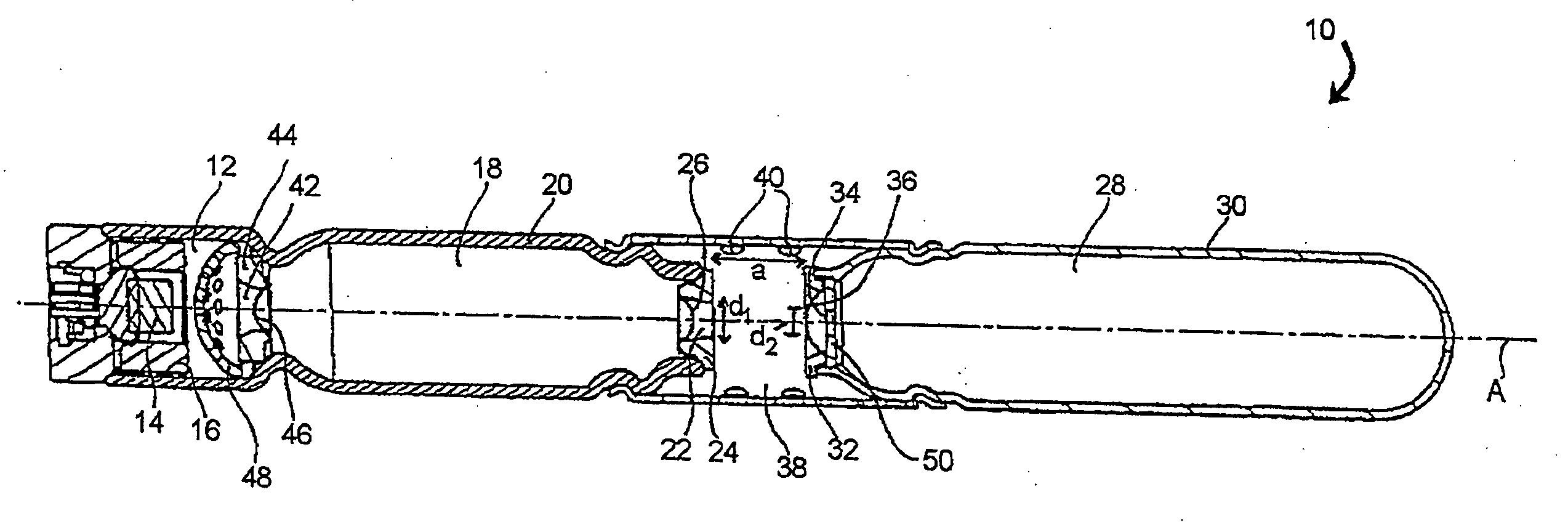
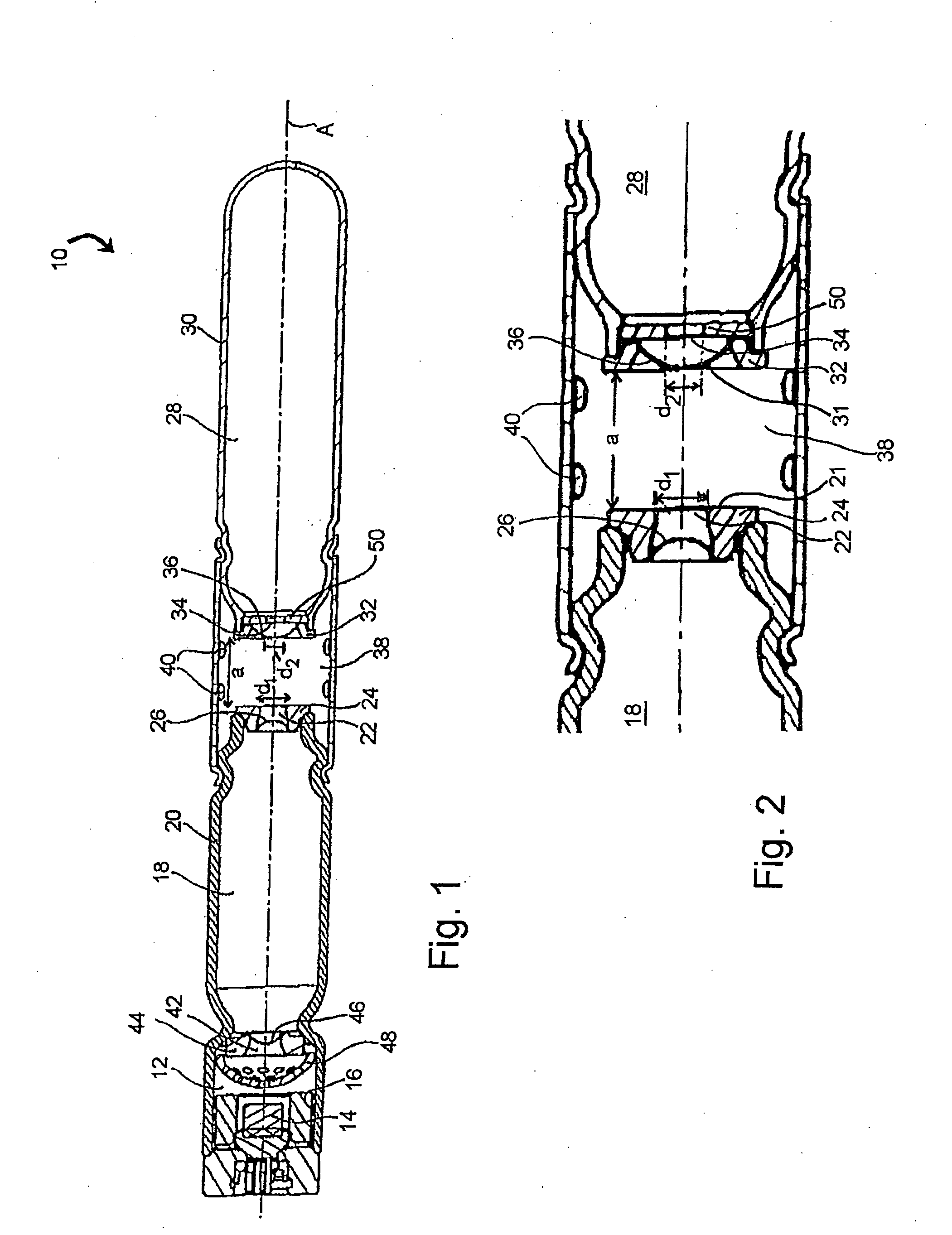
[0023]The Figures illustrate a gas generator 10 according to the invention, in the form of an elongated tubular gas generator which more particularly serves for filling a gas bag in a vehicle occupant restraint system. The gas generator 10 has a combustion chamber 12 with an associated igniter 14 which here is more particularly inserted in the combustion chamber 12. The combustion chamber 12 is filled with a pyrotechnical propellant 16 and, in the axial direction A, is adjacent to a first pressure chamber 18, filled with a compressed gas, which is externally defined by a substantially cylindrical wall 20. The pressure chamber 18 has an opening 22 at a discharge end 21 on a front face, remote from the combustion chamber 12, the opening 22 being delimited by a skirt 24 and closed off by a first diaphragm 26. Provided behind the first pressure chamber 18, as viewed from the combustion chamber 12 in the axial direction A, is a second pressure chamber 28, filled with compressed gas, the ...


PUM


Abstract

A gas generator, in particular for a vehicle occupant restraint system, has a pyrotechnical propellant (16), a combustion chamber (12) filled with the pyrotechnical propellant (16), an igniter (14) associated with the combustion chamber (12), a pressure chamber (18), filled with compressed gas, which is adjacent to the combustion chamber (12) and has a first opening (22) remote from the combustion chamber (12) closed by a first diaphragm (26), the diaphragm (26) being destroyed upon activation of the igniter (14), and a second pressure chamber (28) which is filled with compressed gas and has a second opening (34) closed by a second diaphragm (36). The second diaphragm (36) is likewise destroyed upon activation of the igniter (14), and the openings (22, 34) and the gas volumes of the pressure chambers (18, 28) are adapted so that compressed gas flows out from the second pressure chamber (28) for a longer period than compressed gas from the first pressure chamber (18) to increase a gas supply time of the gas generator (10). Further, a method of activating a vehicle occupant restraint system is described.

Description

TECHNICAL FIELD[0001]The present invention relates to a gas generator, in particular for a vehicle occupant restraint system, including a combustion chamber filled with a pyrotechnical propellant and an igniter associated with the combustion chamber and further including a pressure chamber, filled with compressed gas, which is adjacent to the combustion chamber and has an opening remote from the combustion chamber and closed by a first diaphragm, the diaphragm being destroyed upon activation of the igniter. The present invention further relates to a method of activating a vehicle occupant restraint system.BACKGROUND OF THE INVENTION[0002]A generic gas generator is disclosed in EP 1 544 060 A1. Upon activation of the igniter, the pyrotechnical propellant in the combustion chamber is burned off and the compressed gas generated thereby will destroy a diaphragm arranged between the combustion chamber and the pressure chamber. This produces an abrupt pressure drop by which a so-called sh...

Claims


Application Information

Patent Timeline
Patent Type & Authority Applications(United States)
IPC IPC(8): B60R21/26B60R21/274
CPCB60R21/274B60R21/272
Inventor HERGET, CHRISTIANLAST, DETLEF
Owner TRW AIRBAG SYST
Why Eureka
Try Eureka